
In the third and final part of the series, you'll take the completed shark model and make it animation ready by building a complete rig for the model. Lessons include: creating and parenting joints, adding control curves and constraints, creating custom expressions, skinning the mesh and editing weight influences. At the end, you'll have a complete and versatile rig ready to animate.
1. Creating Joints for Rigging
Step 1
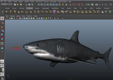
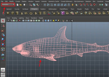
First open the complete textured shark file, which we saved at the end of the last part of the tutorial.

Step 2
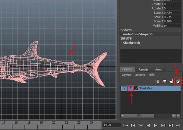
With the shark selected, create a new layer and turn On the template button to make it a template layer. Rename the layer as Shark Mesh.

Step 3
Now turn on Animation mode to start rigging.

Step 4
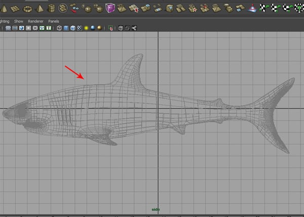
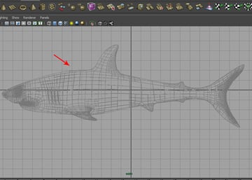
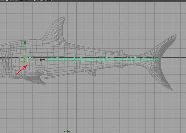
Jump into the Side view to start creating joints inside the shark body.
Step 5
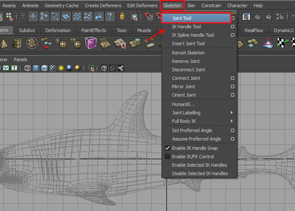
Now go to Skeleton > Joint Tool.

Step 6
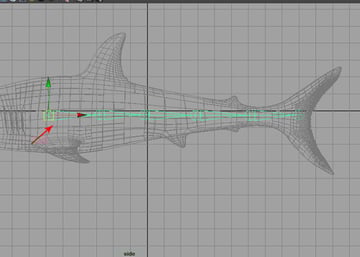
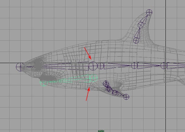
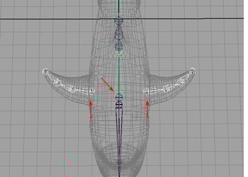
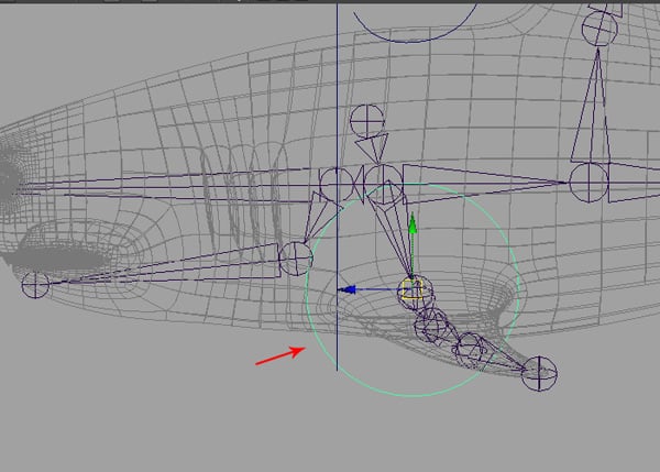
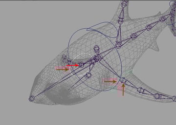
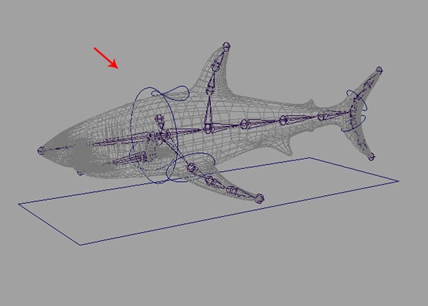
With the Joint Tool selected, start creating joints from the lower front fins by holding the Shift key for a straight line. Draw Six bones up to the tail, as shown in the image below.
Step 7
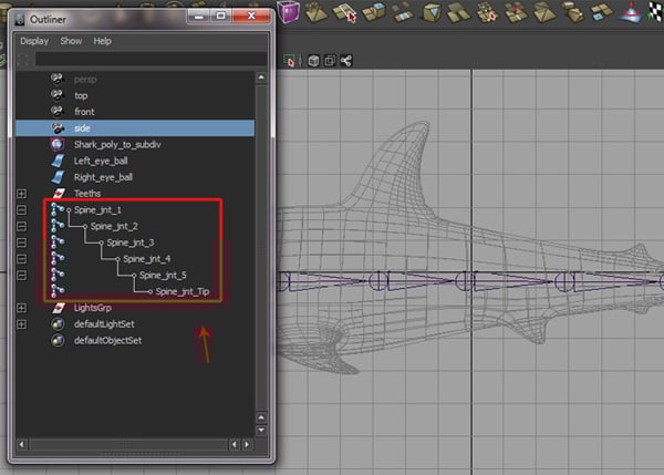
This bone chain will work as the spinal cord. So rename the joints as Spine_jnt_1, Spine_jnt_2, Spine_jnt_3, Spine_jnt_4, Spine_jnt_5 and Spine_jnt_Tip in the Outliner window.

Step 8
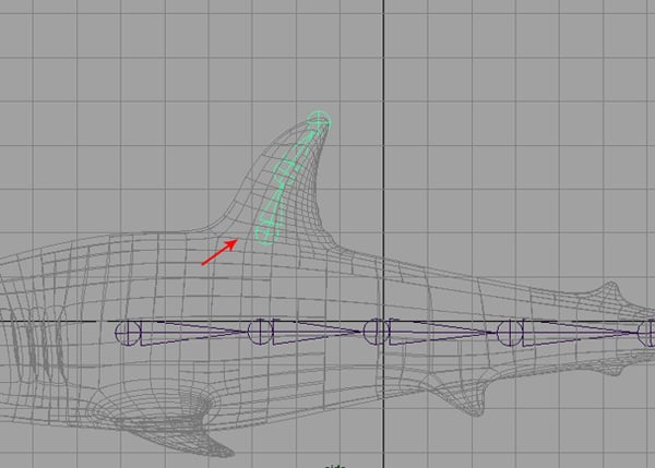
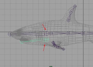
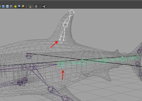
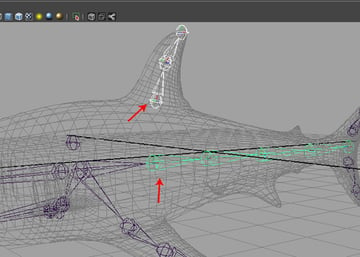
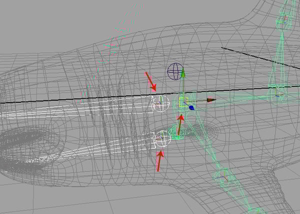
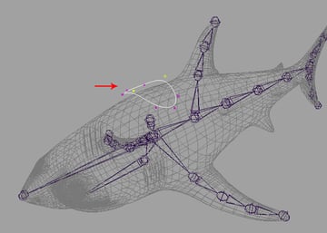
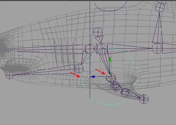
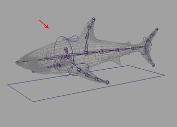
Again, with the Joint Tool selected, create Three more joints for the upper fin, as shown in the image below.
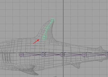
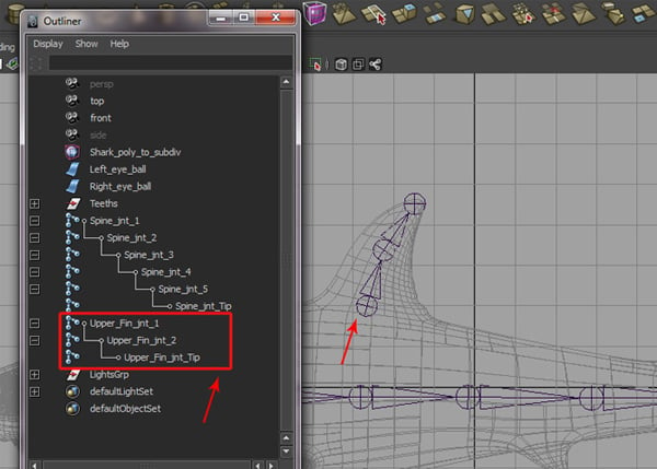
Step 9
Rename these joints as Upper_Fin_jnt_1, Upper_Fin_jnt_2 and Upper_Fin_jnt_Tip.
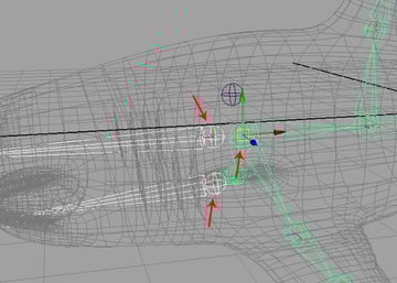
Step 10
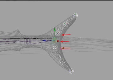
In the same way, create the tail joints and renamed them as Upper_Tail_jnt_1, Upper_Tail_jnt_2, Upper_Tail_jnt_Tip for upper tail mesh, and Lower_Tail_jnt_1, Lower_Tail_jnt_2 and Lower_Tail_jnt_Tip for the lower tail mesh.


Step 11
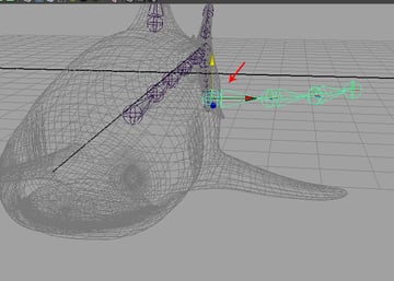
Jump into the Top view, and create joints for the left side fin as shown.
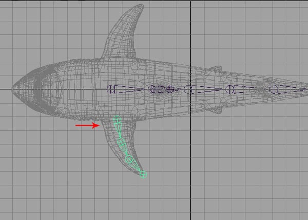

Step 12
If you look in the perspective view, you will find the created joints are not positioned correctly. To correct this, select the joint’s root and move it down in the Y axis to fit the joints inside the fin.

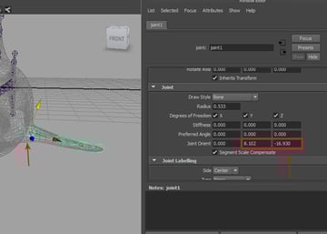
Step 13
You may need to orient the joints according to the mesh flow of the fin. So, press Control-A to open the selected joints’ Attribute panel, and then change the Joint Orient Y and Z axis values to 8.102 and -16.930 respectively. The values may differ in your case.

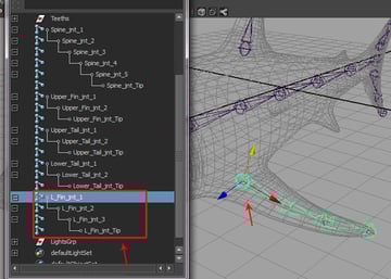
Step 14
Just like before, rename these joints too as L_Fin_jnt_1, L_Fin_jnt_2, L_Fin_jnt_3 and L_Fin_jnt_Tip.

Step 15
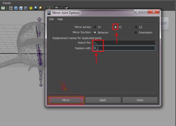
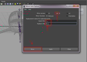
With L_Fin_jnt_1 selected, go to the Skeleton menu and click on the Mirror Joint tool Options box.
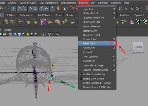

It opens the Mirror Joint Options window. Turn on the YZ radio button for the Mirror across option. Type L_ in the Search for field, and R_ in the Replace with field, and then click on the Mirror button. You'll see the mirrored joints for the right side. Rename the mirrored joints as R_Fin_jnt_1, R_Fin_jnt_2, R_Fin_jnt_3 and R_Fin_jnt_Tip.
Step 16
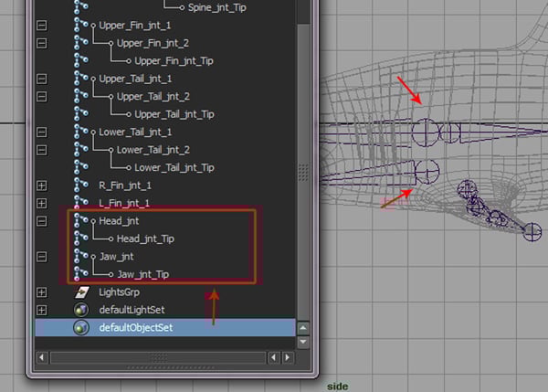
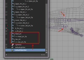
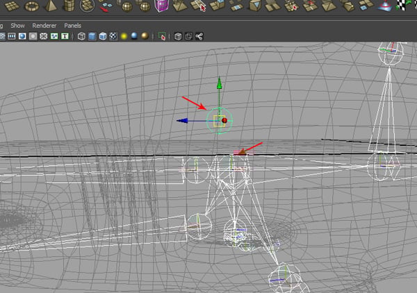
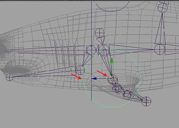
Also create joints for the head and jaw, as shown in the image below.
Step 17
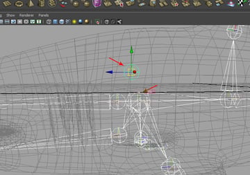
Rename the head joints as Head_jnt and Head_jnt_Tip, and the jaw joints as Jaw_jnt and Jaw_jnt_Tip.
Step 18
Finally create one more joint as the Root joint, as shown in the image below.
2. Parenting Joints
Step 1
Now we will parent the joints with each other. With R_Fin_jnt_1 and L_Fin_jnt_1 selected, hold down Shift and select the SpineBase_jnt, and then press the P key to parent it.

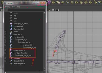
Step 2
In the same way, first select Upper_Fin_jnt_1 and then while pressing and holding the Shift key, select Spine_jnt_2 and press the P key.
Step 3
Now with Upper_Tail_jnt_1 and then Lower_Tail_jnt_1 selected, hold down Shift and select Spine_jnt_Tip and press the P key again.

Step 4
Now with Jaw_jnt and Head_jnt selected, hold down Shift and select SpineBase_jnt and then press P.
Step 5
Finally select the SpineBase_jnt and then select the Root_jnt, and press the P key.
Step 6
We have now completed the parenting process for all joints.


3. Creating Control Curves
Step 1
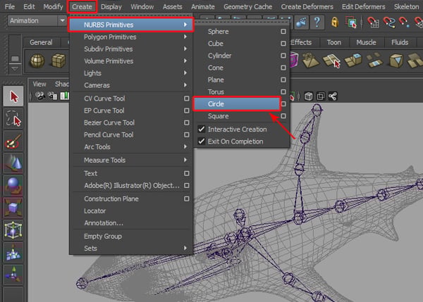
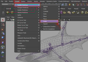
Now we'll start creating control curves. So go to Create > NURBS Primitives > Circle.
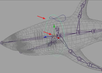
Step 2
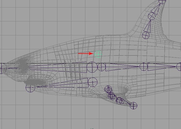
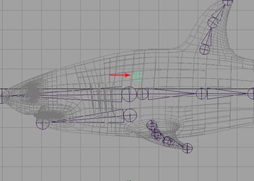
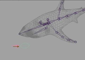
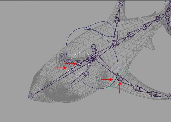
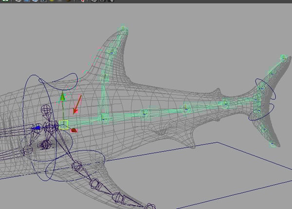
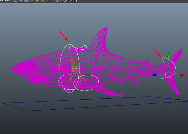
Create a Circle curve in the Perspective view, as shown in the image.

Step 3
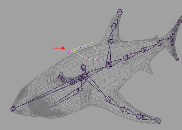
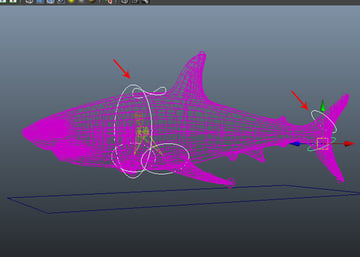
With the Circle selected, move and place it on the top of the shark mesh, and then deform it into something similar to what's shown in the image below. Press F9 to jump into Vertex selection mode, and then deform the vertices to create the shape.
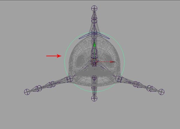
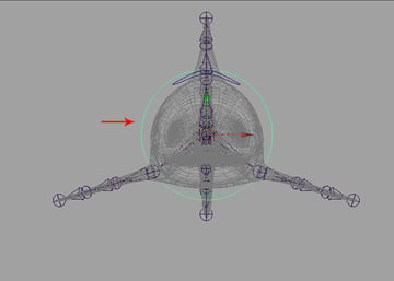
Step 4
Jump into the Front view and then create another big Circle curve, as shown.
Step 5
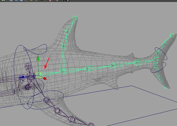
After creating the new circle, jump into the Perspective view and then move and place it around the shark’s head, as shown in the image.

Step 6
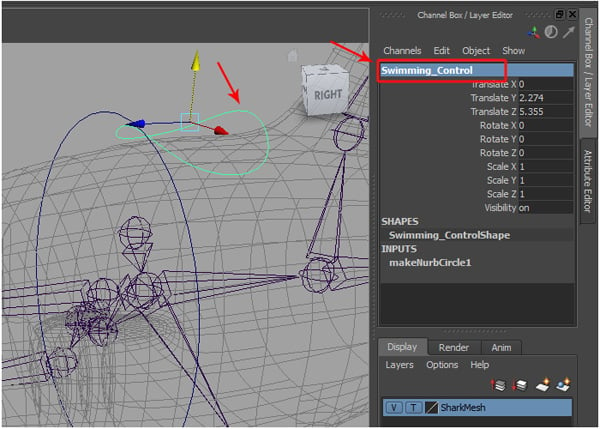
Select the previous circle curve and rename it Swimming_Control in the Channel box.

Step 7
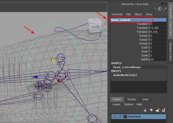
Also select and rename the big circle Head_Control.
Step 8
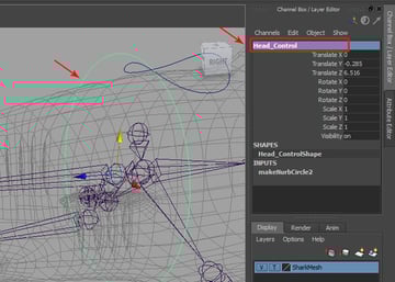
I have also created two more Circle curves and placed them around the upper and lower tail mesh, as shown in the image below. Rename these curves Upper_Tail_Control and Lower_Tail_Control.

Step 9
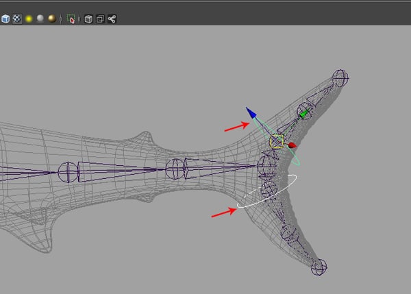
Create one more Circle curve for side fin control, and place it around the side fin area, as shown.

Step 10
With this new circle curve selected, snap it to the L_Fin_jnt_1 by pressing the V key.
Step 11
We have now created the left side fin control, but we also need to create the fin control for the right side as well. So with the left circle selected, press Control-D to duplicate it for the right side fin. Once the right side fin control curve is created, snap it to the R_Fin_jnt_1 by pressing the V key. Rename the left side fin control L_Fin_Control, and the right side fin control R_Fin_Control.
Step 12
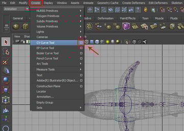
Finally we need to create the global control. So go to Create > CV Curve Tool and click on the Options box.

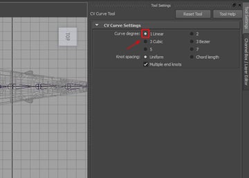
Step 13
This opens the CV Curve Tool settings panel. Here turn on the Curve degree: 1 Linear radio button.

Step 14
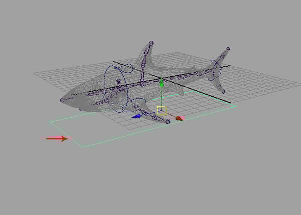
With the CV Curve Tool selected, create a rectangular shape in the Top view, as shown in the following image.


Step 15
Jump into the Perspective view and place it beneath the shark mesh.

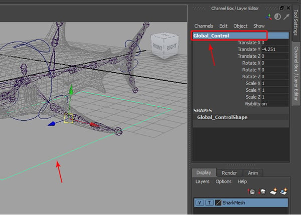
Step 16
Rename this rectangular curve as Global_Control.

Step 17
Now we will delete the history and freeze transformations on all curves. So select all the control curves.

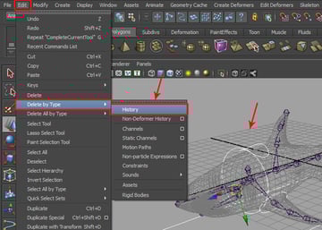
Step 18
With all the control curves selected, go to Edit > Delete by Type > History to delete the history.

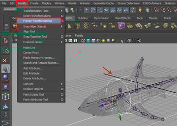
Step 19
With all the control curves still selected, go to Modify > Freeze Transformations.

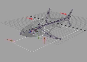
Step 20
We have now created all the control curves for the shark animation controls.
4. Creating Expressions For Spine Joint Rotation
Step 1
We will write an expression for the rotation of the shark’s spine joints. So first select the Spine_jnt_1 as shown in the image below.
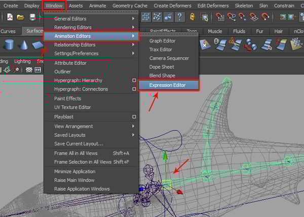
With Spine_jnt_1 selected, go to Window > Animation Editors > Expression Editor.

Step 2
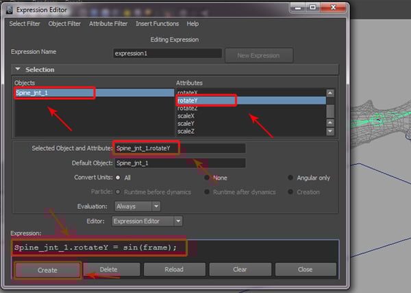
This opens the Expression Editor window. Here select Spine_jnt_1 in the Objects group and Rotate Y in the Attributes group. Then type
Spine_jnt_1.rotateY = sin(frame);
into the Expression box and then click on the Create button, to apply the written expression structure.

Step 3
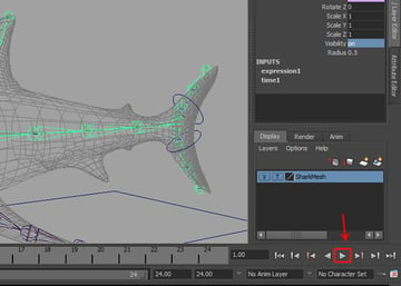
You can see the result by clicking on the Play button. You'll see the spine joints rotate automatically. However the animation is not quite proper, as we need to tweak the expression for follow-through.

Step 4
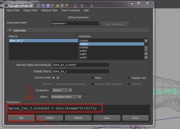
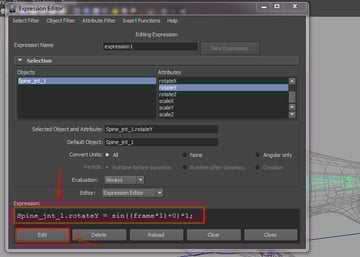
So with the same Spine_jnt_1 selected in the Expression Editor, re-type
Spine_jnt_1.rotateY = sin ((frame*1)+0)*1;
and then click on the Edit button to update the new expression.
Step 5
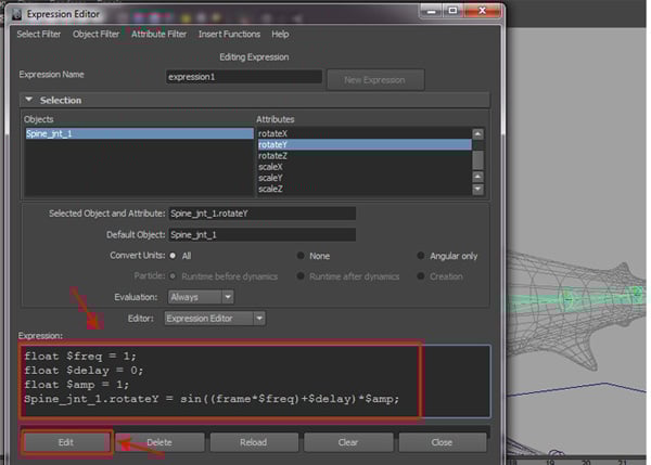
Now we have to create a variable for controlling the joints for a realistic animation. So with Spine_jnt_1 selected again, rewrite the expression as
float $freq = 1;

float $delay = 0;

float $amp = 1;

Spine_jnt_1.rotateY = sin((frame*$freq)+$delay)*$amp;
Finally click on the Edit button to update the new edited expression.

Step 6
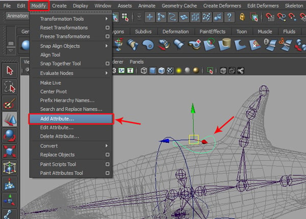
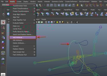
Now we'll create some custom attributes. So with Swimming_Control selected, go to Modify > Add Attribute.

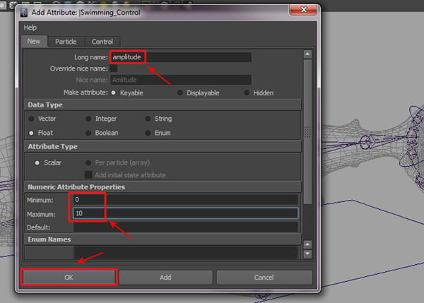
This opens the Add Attribute window, in the Long name field write amplitude. And set the Numeric Attribute Properties for Minimum to 0, and Maximum to 10. Then click on the OK button.

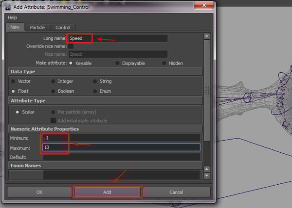
Again in the Long name field type Speed, and set the Minimum value to .1 and the Maximum value to 10, and then click on the Add button.

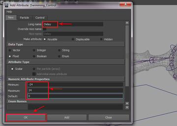
And finally, in the Long name field type Delay, and then set the Minimum value to -24 and the Maximum value to 24, and click on OK.

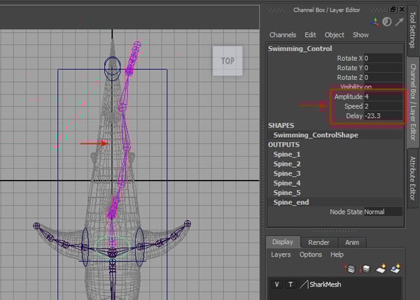
Step 7
Now after selecting the Swimming_Control, you will see three new customs attributes: Amplitude, Speed and Delay in the Channel Box.


Step 8
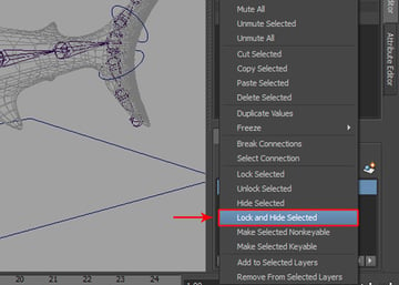
Now with the Swimming_Control selected in the Channel Editor, select all the Translate and Scale parameters.
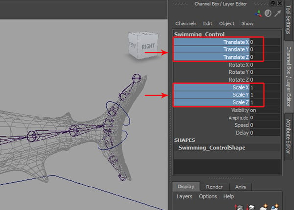
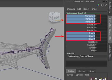
Right Click on them and select Lock and Hide Selected from the fly-out menu.

Step 9
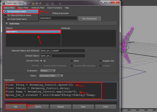
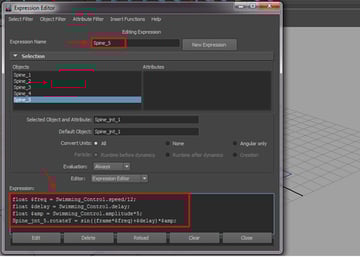
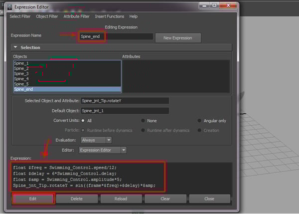
Now open the Expression Editor and type the following expression in the expression text box.
float $freq = Swimming_Control.speed/12;

float $delay = Swimming_Control.delay;

float $amp = Swimming_Control.amplitude*5;

Spine_jnt_1.rotateY = sin((frame*$freq)+$delay)*$amp;
Finally click on the Edit button.

Step 10
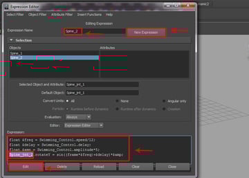
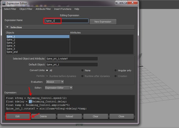
We now need to write an expression for each spine joint. So select all the written expressions and rename the expression as Spine_1, and press the Edit button.


Step 11
Next, click on the New Expression button and type Spine_2 as the expression name. Then paste the copied expression text into the Expression field box, and replace Spine_jnt_1 with Spine_jnt_2. Finally click on the Edit button.

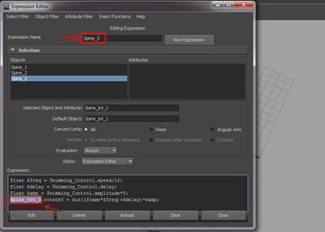
Step 12
Do the same thing for next spine joint. Click on the New Expression button and type Spine_3 as the expression name. Then paste the copied expression text into the Expression field box, and replace Spine_jnt_1 with Spine_jnt_3. And click on the Edit button.

Step 13
Using the same process, I have also created expressions for Spine_jnt_4 and Spine_jnt_5.

Step 14
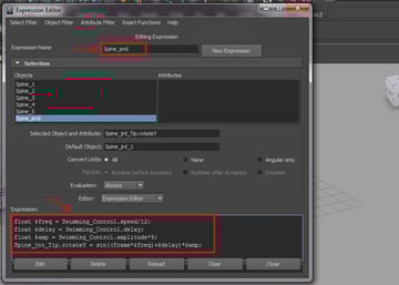
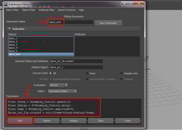
Finally for the end spine joint, click on the New Expression button and type Spine_end as the expression name. Then paste the copied expression text into the Expression field box, and replace Spine_jnt_1 with Spine_jnt_Tip. And finally click on the Edit button.

Step 15
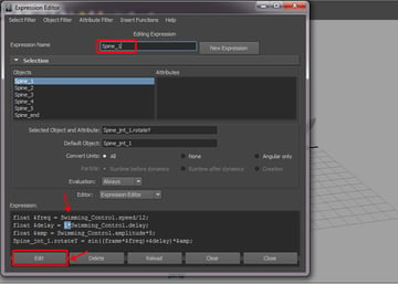
After doing this, I've checked the attributes for the animation control. It works fine, but we can’t control the delay attributes. So we have to multiply the delay values for each spine joint. So we keep the 1* in place for the Spine_1 expression, and re-number the values up to 6* for the remaining five joints, as shown in the image below.
Step 16
Through this process, we have now changed all the Spine_1 to Spine_end expressions one by one with a float delay.
Step 17
Now, check the Custom Attributes. You can see all the controls for the Swimming Control. We have now completed the expressions for the spine joints.

5. Creating Constrain Controls
Step 1
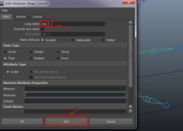
Before creating the constraint controls, I have hidden the shark mesh in the Layer Editor. Now with Head_Control selected, go to Modify > Add Attribute.

In the Add Attribute settings window, type Jaw X in the Long name field and then click on the Add button, to add a new attribute.

Step 2
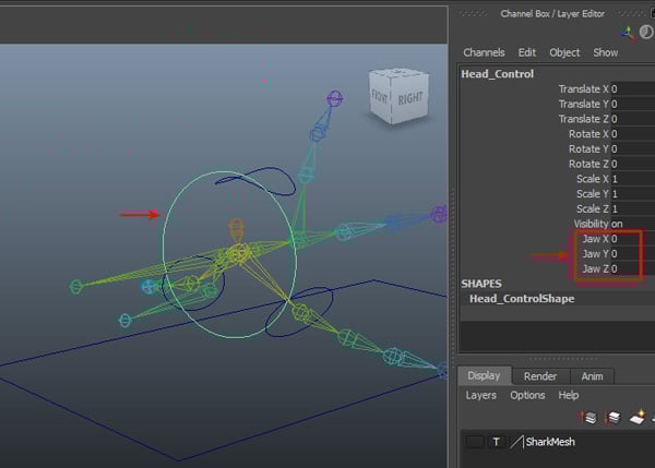
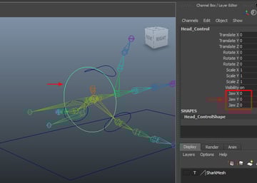
Following this process, create all three custom attributes respectively: Jaw X, Jaw Y and Jaw Z.
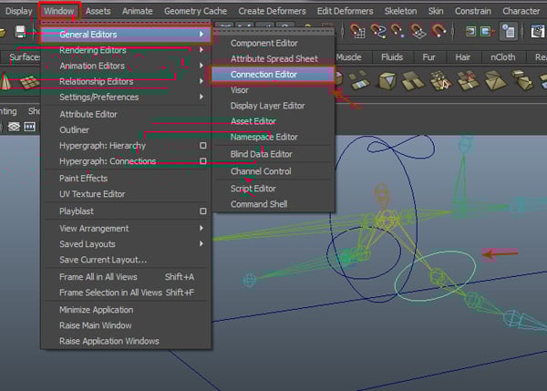
Step 2
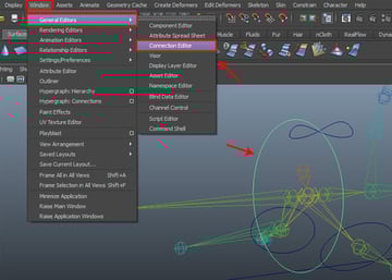
Now with Head_Control selected, go to Window > General Editors > Connection Editor.
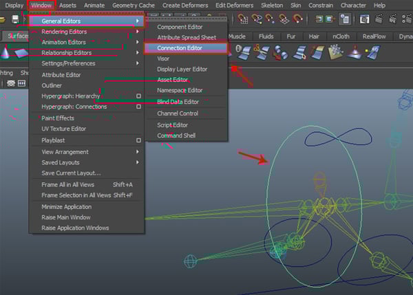
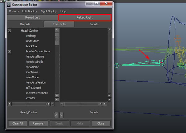
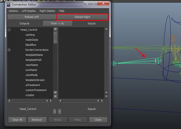
In the Connection Editor, we can see Head_Control in the Outputs group. First select Jaw_jnt in the viewport and then click on Reload Right.
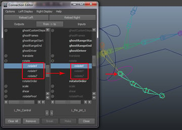
Step 4
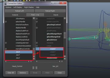
After loading Jaw_jnt, click on Head_Control Jaw X to Jaw_jnt rotateX, Head_Control Jaw Y to Jaw_jnt rotateY and Head_Control Jaw Z to Jaw_jnt rotateZ.

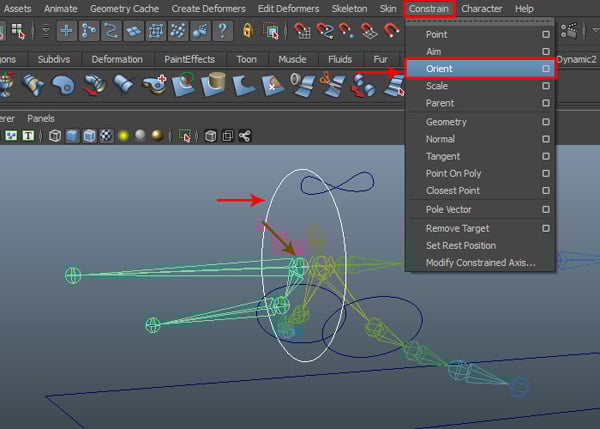
Step 5
With Head_Control selected, first select Head_jnt and then go to Constrain > Orient.

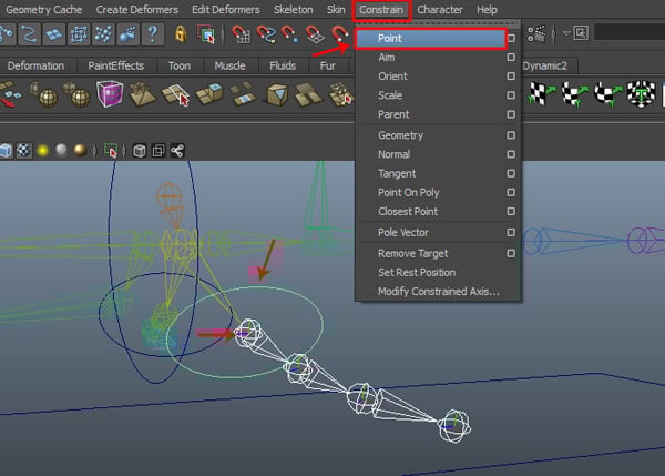
Step 6
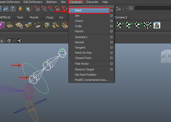
Next, select L_Fin_jnt_1 and then select L_Fin_Control, and go to Constrain > Point tool.
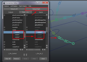
Step 7
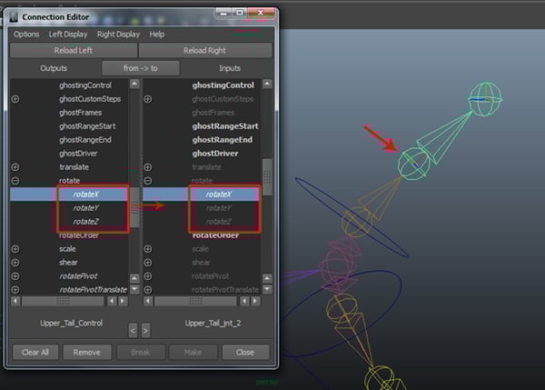
After applying a point constrain, select L_Fin_Control and then go to Window > General Editor > Connection Editor.

This opens the Connection Editor. Select L_Fin_jnt_1 in the viewport and then load it in the right side, by clicking the Reload Right button. And then connect all three rotate X, Y and Z inputs for both sides.

Step 8
Now select L_Fin_jnt_2 and then click on the Reload Right button, and do same as we did previously.

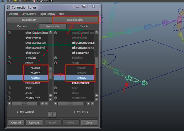
Step 9
Now select L_Fin_jnt_3 and then click on the Reload Right button, and connect them as we did previously.

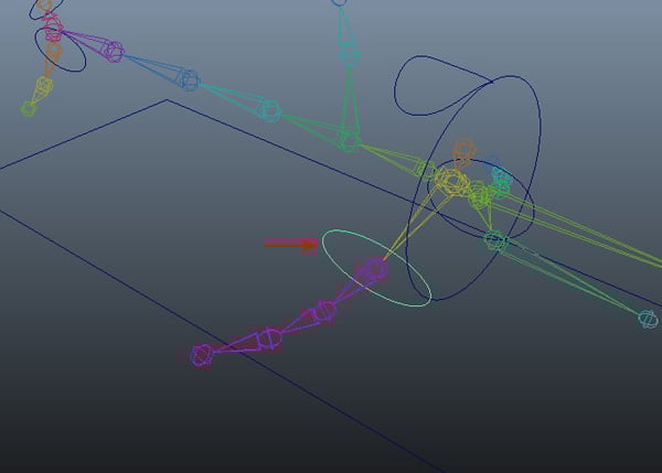
Step 10
Following the same process, I have connected the right side and applied a Point Constrain, just like we did for the left side joints.
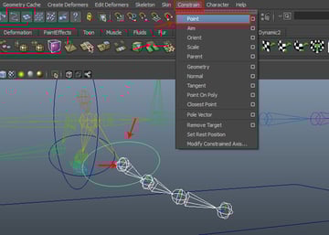
Step 11
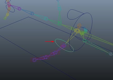
Now we'll do same with the upper and lower tails. So with Upper_Tail_jnt_1 selected first, select the Upper_Tail_Control and then go to Constrain > Point.

Step 12
Now with the Upper_Tail_Control selected, open the Connection Editor and then reload the right side with the Upper_Tail_jnt_1, and then connect rotate X, Y and Z.


In the same way, connect Upper_Tail_jnt_2 also.

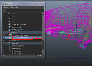
Step 13
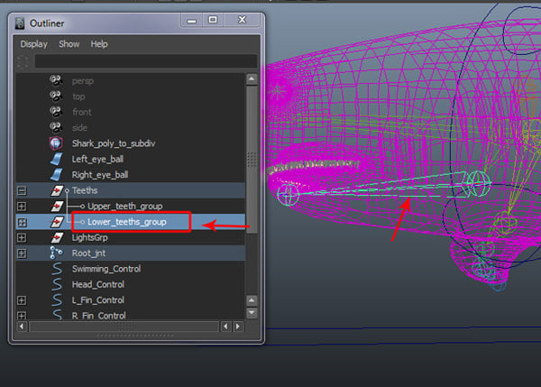
Open the Outliner window. Here select the Lower_teeth_group and while holding down Control, select the Jaw_jnt and then press the P key to parent.
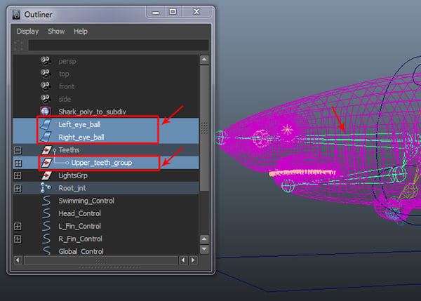
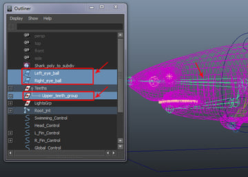
Step 14
First select Left_eye_ball, Right_eye_ball and the Lower_teeth_group, and then select the Head_jnt and press P to parent them together.
6. Creating the Global Controls
Step 1
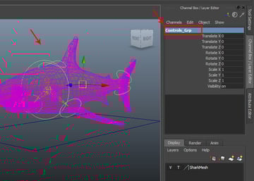
Select all the control curves, expect for the Global Control curve and press G to group them.
After making the group of the controls, rename it Controls_Grp in the Channel Box.

Step 2
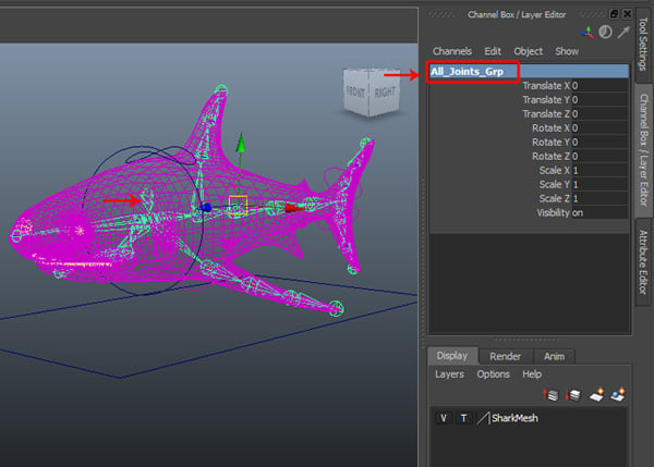
Now select the Root_jnt and press G to make it a group of joints. Rename it All_Joints_Grp.

Step 3
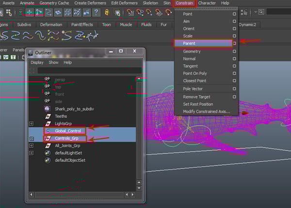
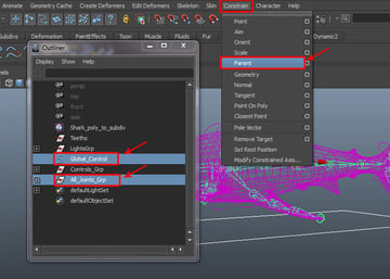
Now in the Outliner window, first select the Global_Control and then select the Controls_Grp and go to Constrain > Scale Constrain.
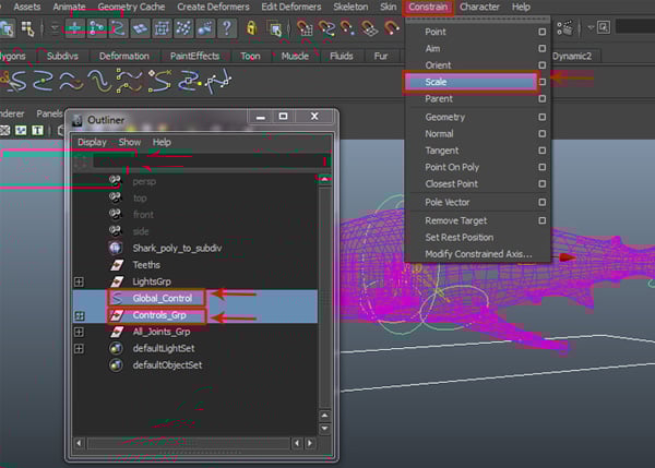

With the same controls still selected, go to Constrain > Parent Constrain this time.

Step 4
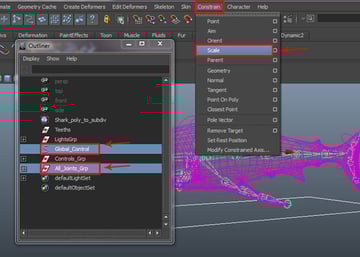
Now, select the Global_Control and then select the All_Joints_Grp, and go to Constrain > Scale Constrain.
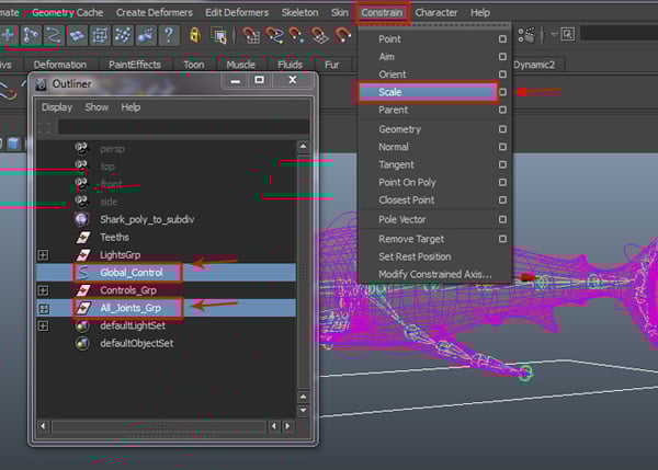
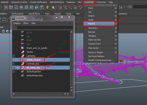
Again with the same controls still selected, go to Constrain > Parent Constrain this time.
7. Applying Skinning and Editing Weights
Step 1
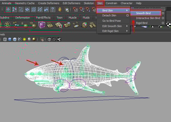
With the shark mesh and Root_jnt selected together, go to Skin > Bind Skin > Smooth Bind.

Step 2
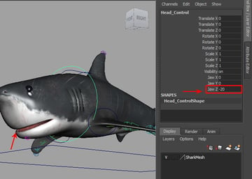
Now select the Head_Control and then set the Jaw Z value to -20. You'll see deformation around the mouth area, but it is not correct. We have to balance and adjust the skin weights according to the respective joints.

Step 3
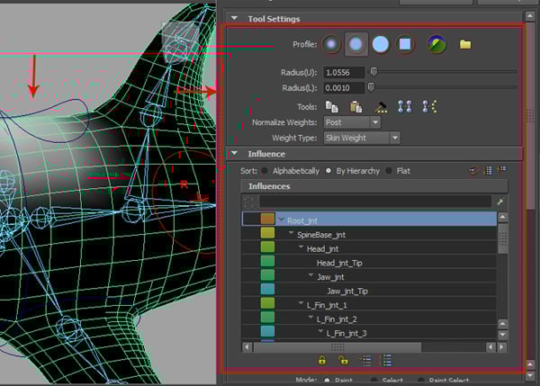
For adjusting skin weights, go to Skin > Edit Smooth Skin > Paint Skin Weight Tool and click on the Options box.
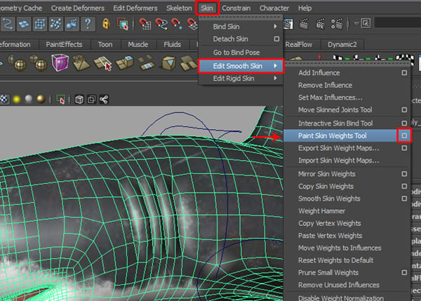

This opens the Paint Skin Weight Attribute Editor window. You can select the joints individually and then reduce, or add skin weights as needed.

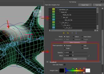
Step 4
For adjusting and painting weights, scroll down the attributes list and paint and adjust weights using the Add and Replace options as required.

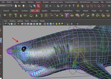
Step 5
In this case, we can also use the Component Editor for better controls over the skin weights. So with the shark mesh selected, turn on the Component button on the status bar, as shown in the image below.

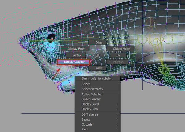
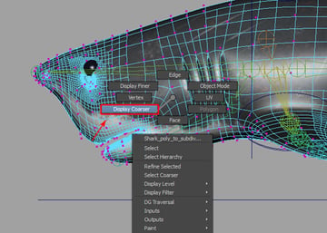
Now Right Click on the shark mesh, and select Display Coarser.
Step 6
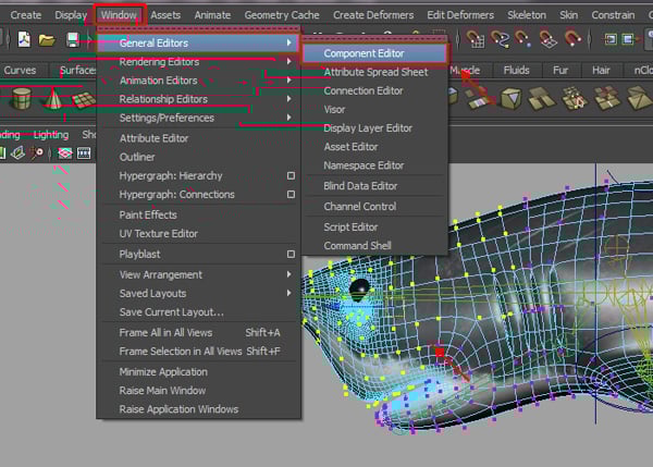
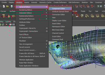
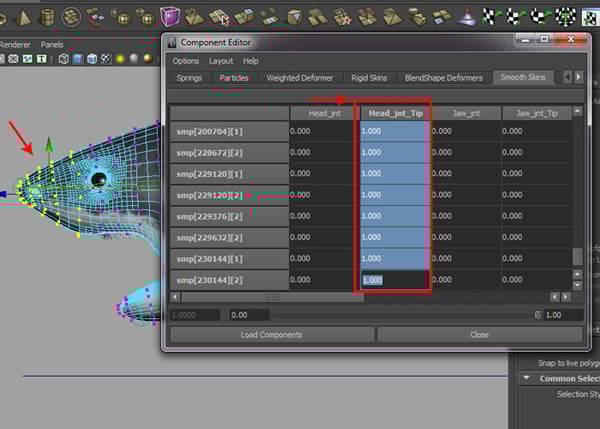
With the verticies of the upper head area selected, go to Window > General Editor > Component Editor.
Step 7
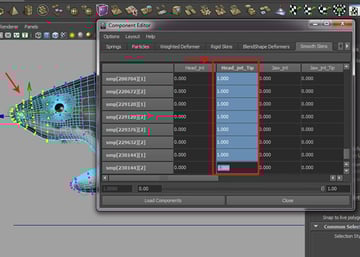
In the Component Editor, select the entire column of weight boxes and enter a value of 1, and then press the Enter key. You'll notice, all the selected vertices have shifted a bit upward.
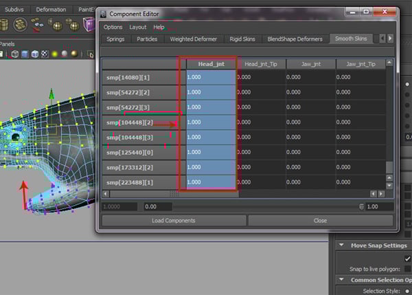

Again, select some more vertices around the nose area, and enter the same value of 1 for the entire column of the Head_jnt_Tip, and then press the Enter key.
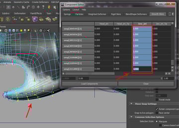
Step 8
Following the same process, select the verticies of the lower jaw, and set a value of 1 under the Jaw_jnt joint column, and press Enter again.

Step 9
We have now properly adjusted the skin weights for all the joints.

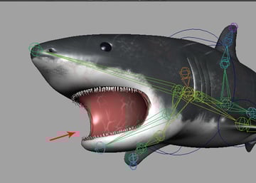
Conclusion
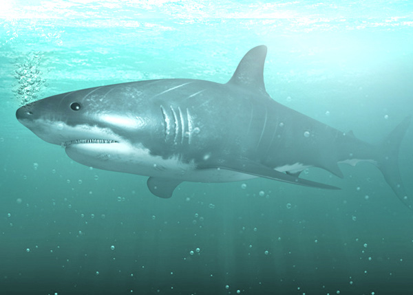
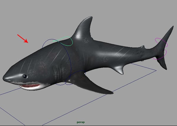
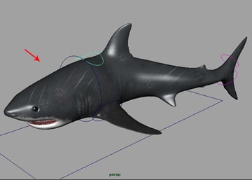
Below is the complete shark character, fully rigged and ready for animation. I hope you have liked this series.
 By
By


