

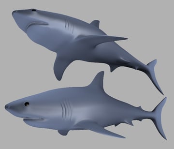
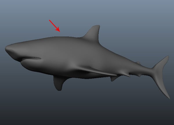
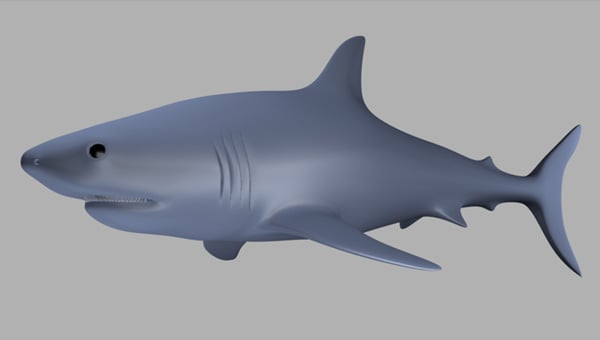
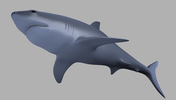
With the recent wrap up of our Realistic Shark in 3D Studio Max series, we're happy to launch a follow up project for our Maya users. Soni Kumari has created a second, more detailed version of the tutorial. Where she'll once again guide readers through the process of Modeling, UVMapping, Texturing, Rigging and Rendering a believable and lifelike shark, this time using Maya's exceptional toolset.
Additional Files:
1. Introduction & Scene Setup
Step 1
Before starting to model the shark, let me tell you a little about Subdivision surfaces and Polygon modeling. In Maya, Subdivision surfaces are a unique surface type available for modeling that possess characteristics of both polygon, and NURBS surface types. As per NURBS surfaces, subdivision surfaces are capable of producing smooth organic forms and can be shaped using relatively few control vertices. As per polygon surfaces, subdivision surfaces allow you to extrude specific areas and create detail in your surfaces when it is required.
This is accomplished by having the ability to work at different component levels of detail on the subdivision surface. You can switch between the different levels of detail as often as necessary, and you can convert existing NURBS and polygon surface types to subdivision surfaces and vice versa. We'll first start with the polygon modeling process and then convert it into a Subdiv surface so we can use the Subdiv surface Controls.
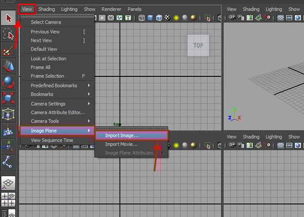
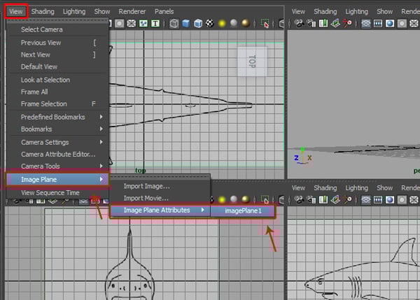
First we have to load in all three references images to use as our background image reference. So go to the View menu on the panel menu bar, and select the Import Image option inside the Image Plane submenu.

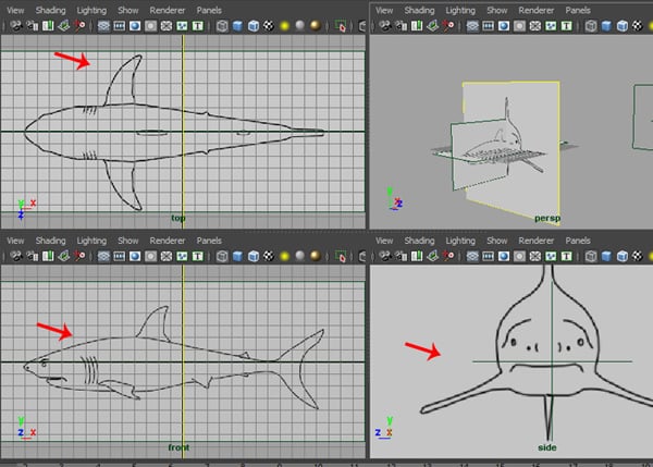
Using this method, I have imported all three reference images into the background.
You can adjust the attributes of each image by going to to View > Image Plane > Image Plane Attribute.

Step 2
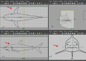
In the Image Plane Attribute settings, use the Center X,Y,Z and Width values as needed to match the images.

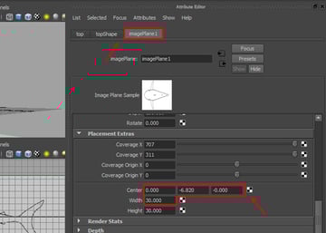
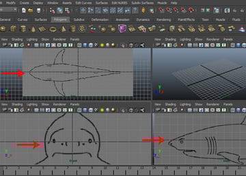
The scene should look like this after matching the reference images.

2. Modeling the Body
Step 1
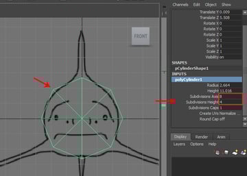
Now to begin the modeling process, create a Cylinder poly primitive in the Front view.


Step 2
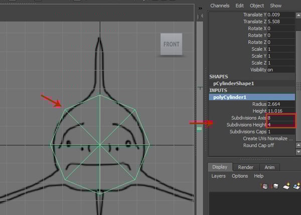
Now with the polyCylinder selected, press Control-A to open its Channels Settings attributes. Go to the INPUTS tab and keep the Subdivisions Axis value at 8, and the Subdivisions Height value at 4.
Step 3
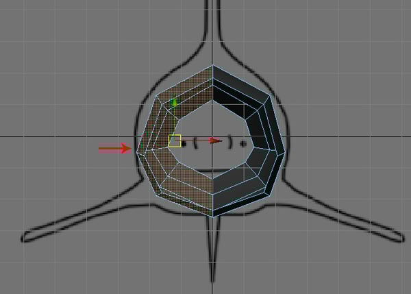
Then press the F9 key to jump into Vertex selection mode, and arrange the vertices according to the Front and Side reference images.
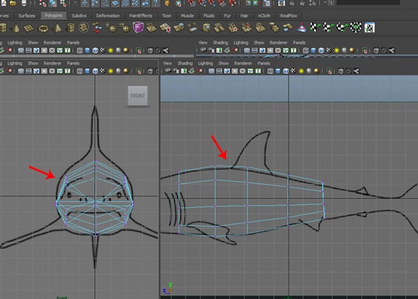
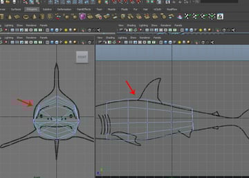
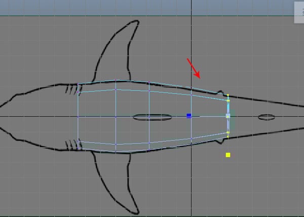
Arrange the vertices according to the Top reference image also.

Step 4
Now in the Perspective view and with the polyCylinder mesh still selected, press F11 to jump into Face selection mode, and select the front and the back cap faces. Then press the Delete key to delete the selected faces.
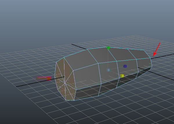

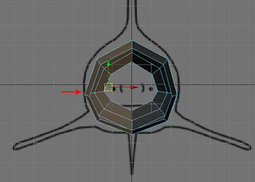
Next, jump into the Front view and select half of polyCylinder mesh. And press the Delete key to delete the selected faces.
Step 5
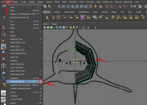
After deleting half of the side faces, select the remaining half and press F8 key to jump into Object selection mode. Then go to the Edit menu and click on the Duplicate Special options box.

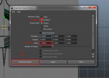
Step 6
In the Duplicate Special Options, turn on the Instance radio button and keep the Scale value for the X Axis at -1.00, and then click on the Duplicate Special button.

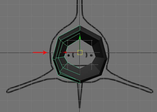
Step 7
As you can see, an instanced copy of the mesh has been created along the -X Axis.
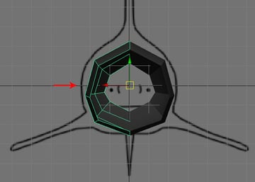
Step 8
Now press F10 to enter Edge selection mode, and select one half of the border edge on the front left side.

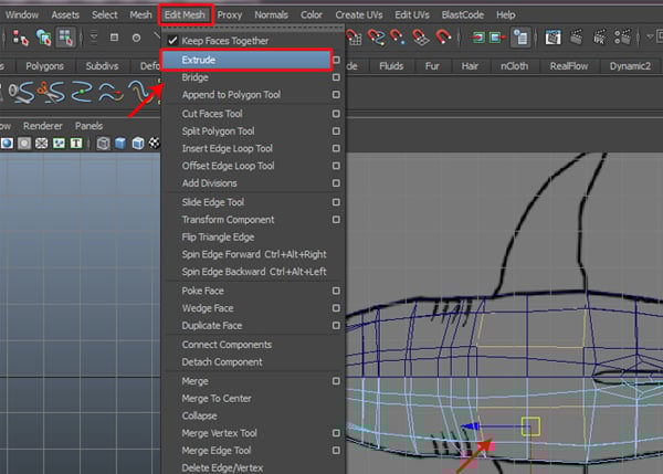
Step 9
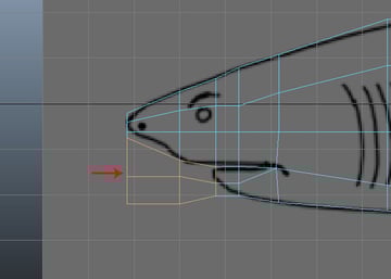
Jump into the Side view, go to the Edit Mesh menu and click on the Extrude command.
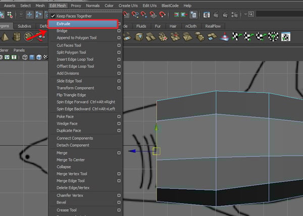

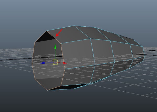
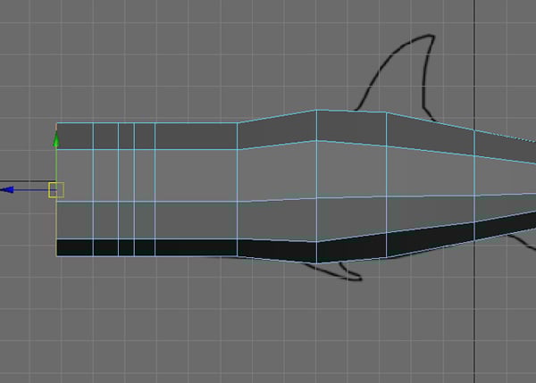
Step 10
Using the same procedure, I have extruded the border edge five times towards the shark’s head, as shown in the image below.
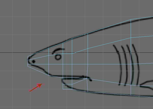
Step 11
While still in the same Side view, press the 4 key to convert the selected mesh into Wireframe mode, and also press F9 to jump into Vertex selection mode. Then try to arrange the vertices according to the reference image, as shown.

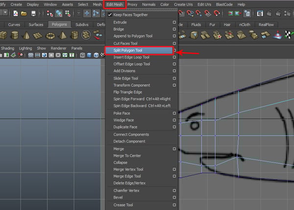
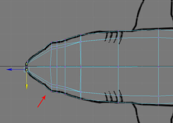
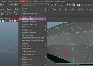
Step 12
Once done, go to the Edit Mesh menu and select the Split Polygon Tool.

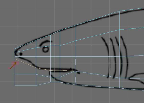
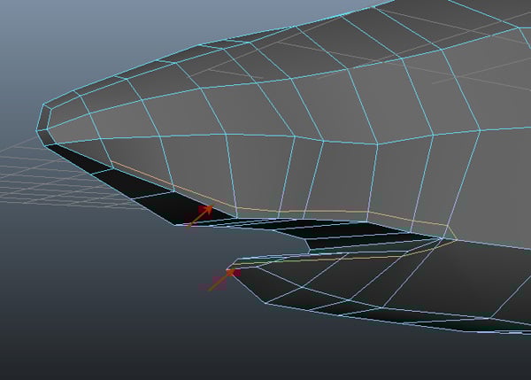
Step 13
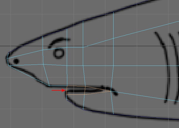
With the Split Polygon Tool selected, split and divide the faces indicated below for the upper and lower parts of the shark's mouth.
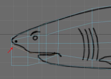
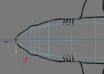
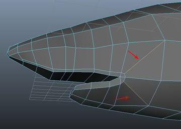
Step 14
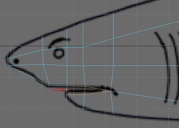
Press F11 to jump back into Face selection mode, and then with the four lower unnecessary faces selected (marked below), press the Delete key to delete them.
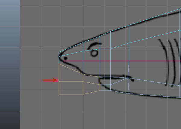
After deleting the faces, it should look something like this.

Step 15
Also jump into the Top view and arrange the vertices by pressing F9.
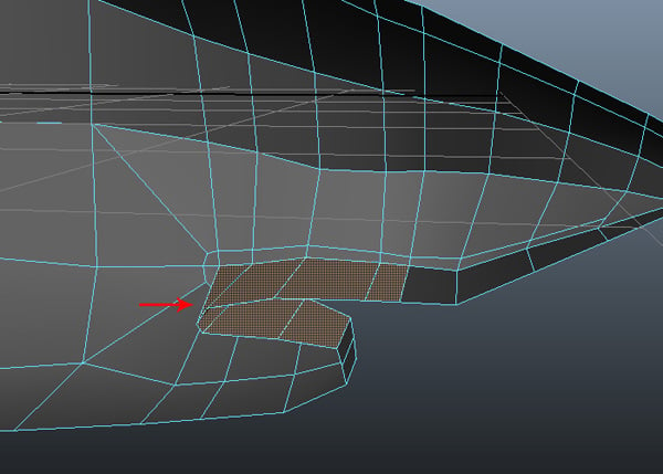
Step 16
Once again press the F11 to enter Face selection mode, and then select the faces inside the mouth (indicated below), and Delete them.
Step 17
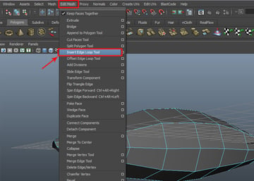
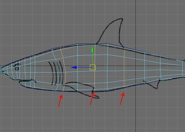
Now we need to insert several edge loops to add more detail. Go to the Edit Mesh menu and select the Insert Edge Loop Tool.

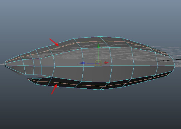
With the Insert Edge Loop Tool selected, insert two edge loops along the upper and lower body as shown in the image below.

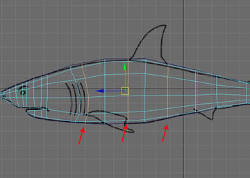
Step 18
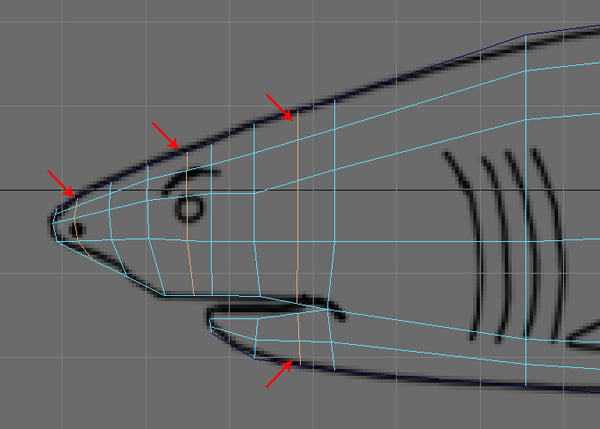
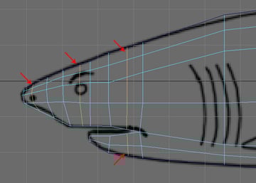
Jump into the Side view and insert four more edge loops around the mouth area, as shown.
3. Modeling the Tail
Step 1
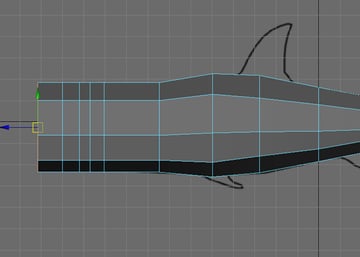
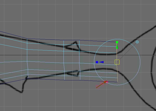
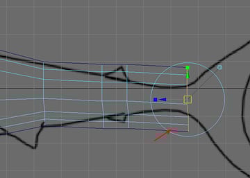
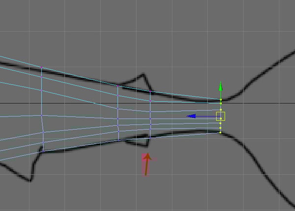
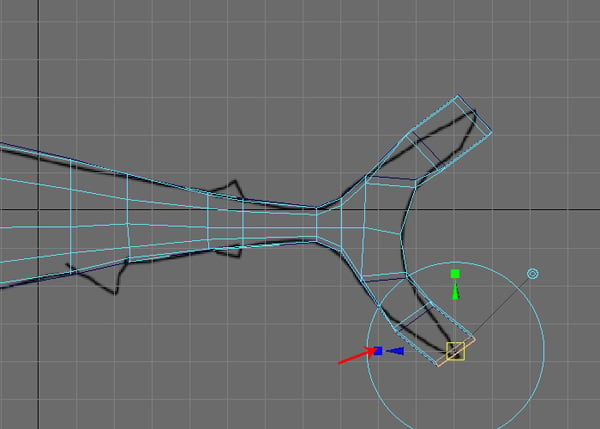
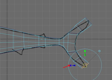
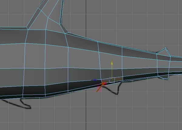
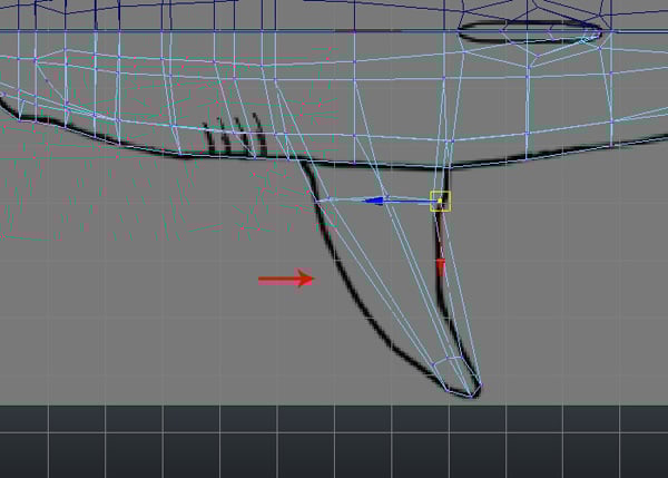
Now Extrude the back border edge three times for the shark's tail.
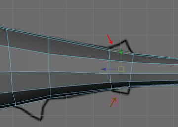
Step 2
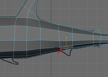
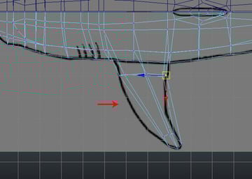
Press F9 for Vertex selection mode, and then arrange the tail vertices according to the reference image.
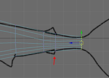
Also jump into the Top view, and arrange the vertices here too according to the reference image.
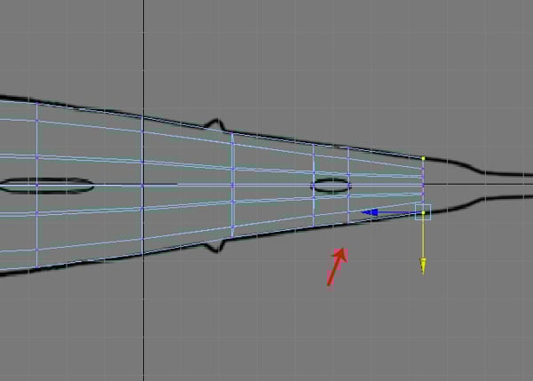
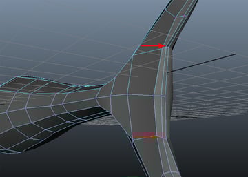
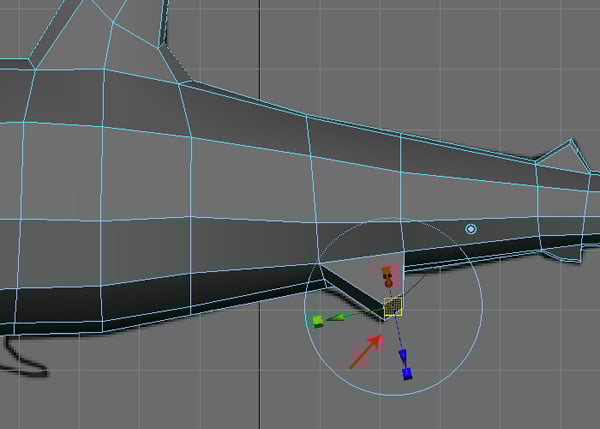
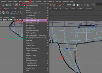
Step 3
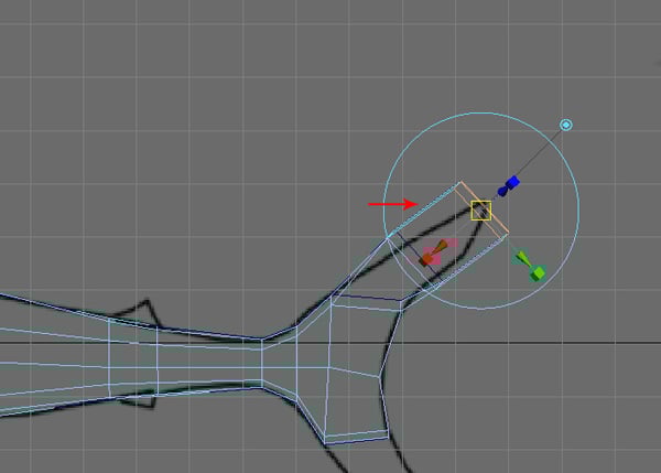
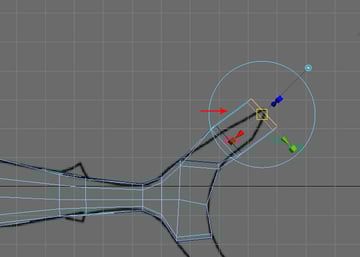
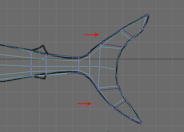
Now Extrude the tail edges three more times to the end corner, as shown in the following image.
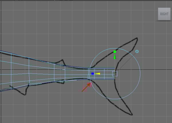
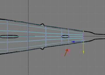
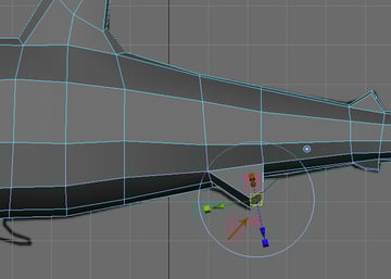
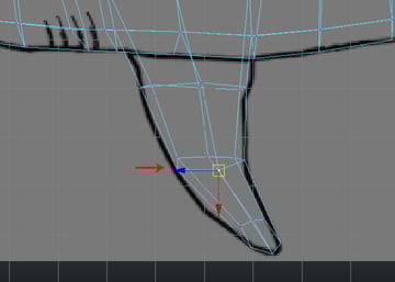
Step 4
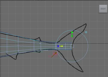
Press F9 to enter Vertex selection mode, and then expand and arrange the vertices according to the reference image.

Step 5
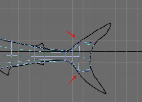
Jump into the Perspective view now and press F11 to enter Face selection mode. And then select the both top faces.

Step 6
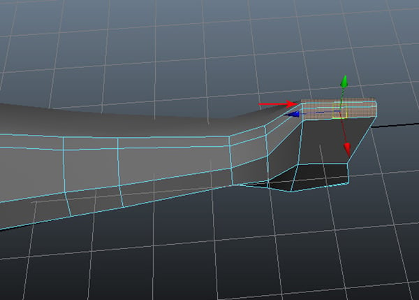
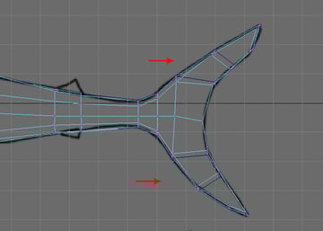
With the top faces selected, jump into the Side view and then using the Extrude command, Extrude them two times towards the end of the tail fin.
Do the same with the lower tail faces also.
Step 7
After extruding, press the F9 key to enter front left side Vertex selection mode, and arrange the tail fins according to shape shown on the reference image.
Step 8
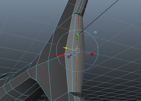
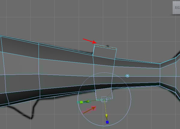
Now go back to the Perspective view and focus on the back of the tail mesh. Here we need to fill the gap between the polygons, so first press F10 for Edge selection mode and then select the two border edges, as shown in the image below.
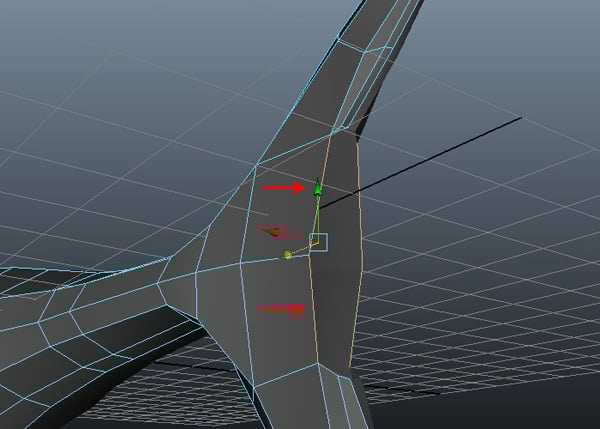
Step 9
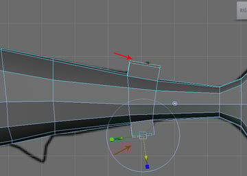
With the edges selected, Extrude them two times while maintaining the edge loops.
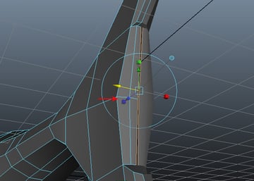
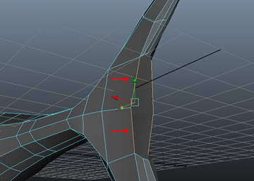
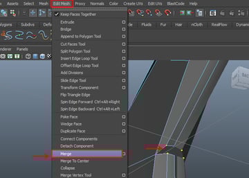
Step 10
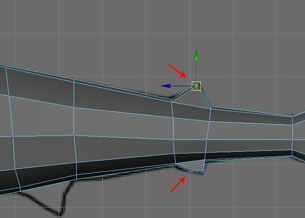
Now we need to weld the vertices. With both of the vertices selected, go to the Edit Mesh menu and choose the Merge command to weld the selected vertices together.

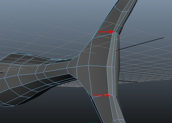
Step 11
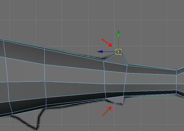
Following the same process, weld the vertices of the lower tail also.
4. Creating the Fins
Step 1
We need some more faces to create the dorsal fins. With the Insert Edge Loop Tool selected, insert three edge loops around the fin areas as shown in the image below.
Step 2
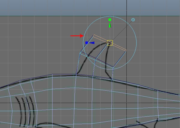
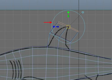
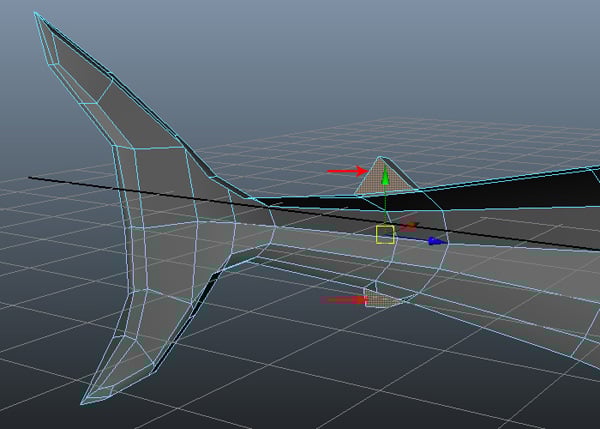
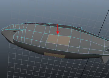
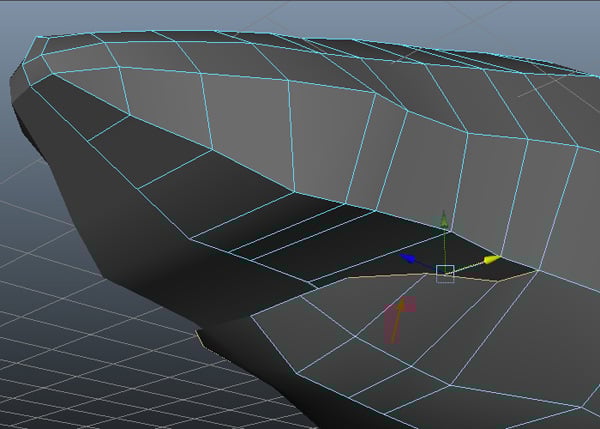
Now in the Side view, press F11 to enter Face selection mode and select the top faces around the area of the dorsal fin.
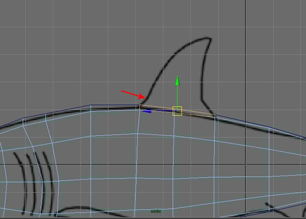

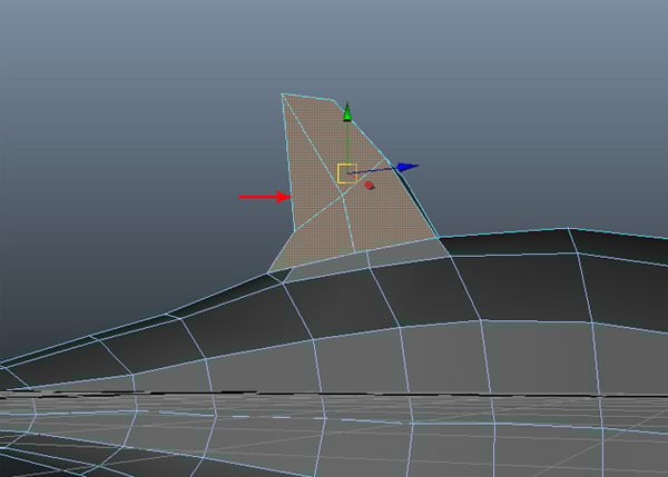
Step 3
With the faces selected, Extrude them upward two times as shown.
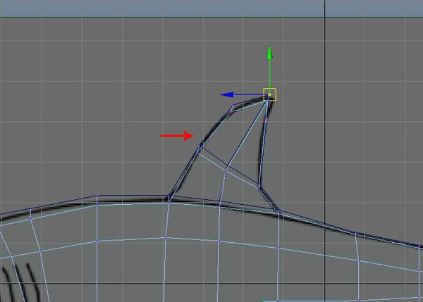
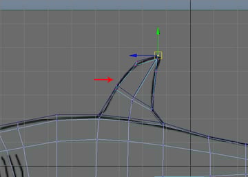
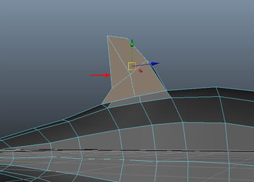
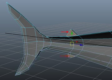
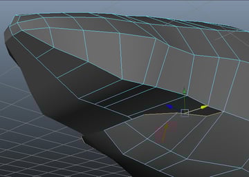
Step 4
Again press F9 to access Vertex selection mode, and then arrange the vertices according to the background image.
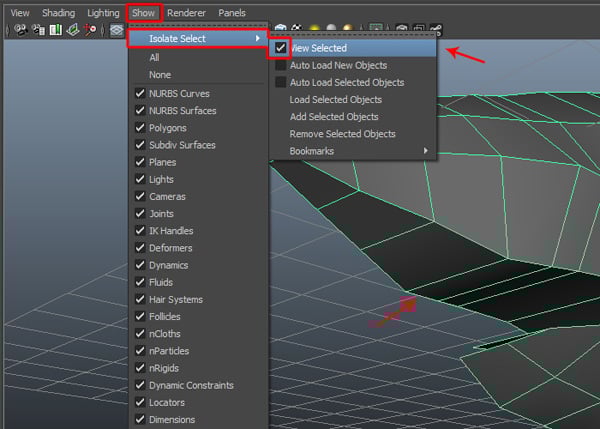
Step 5
While in the Perspective view, select half of the shark model. Then go to the Show menu, and check on the View Selected check box inside the Isolate Select submenu. This will isolate the selected half of the shark body.
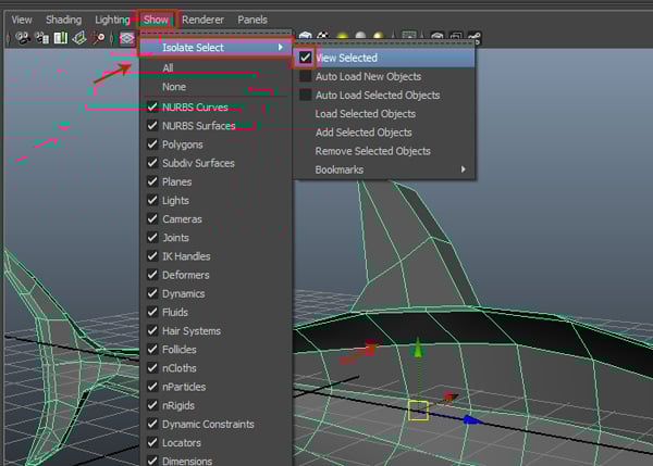

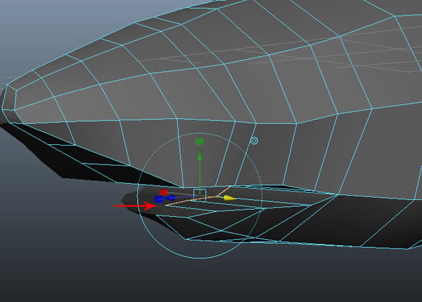
Step 6
We did this because we need to delete some of the unwanted faces which are hidden inside the body. You can see the dorsal fin faces are still there, which can create problem. Hence we need to delete these faces. So press F11 key for Face selection mode and select the dorsal fin faces from inside. Then press the Delete key to delete them.
Step 7
Now we will make the anal fins of the shark. Select the top and bottom faces around these fins according to the reference image.

Step 8
With the faces selected, apply the Extrude command and then Extrude them once.
Step 9
Back in Vertex selection mode, arrange the vertices properly.
Step 10
Back in the Perspective view. Select the inside faces of the anal fins and then Delete them, as we did previously with the dorsal fin.
Step 11
After that, bring the vertices closer to each other and make the required adjustments.
Step 12
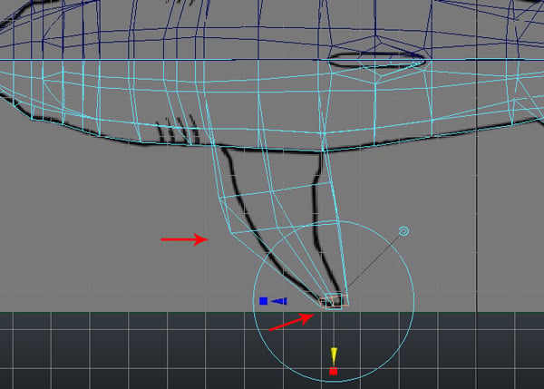
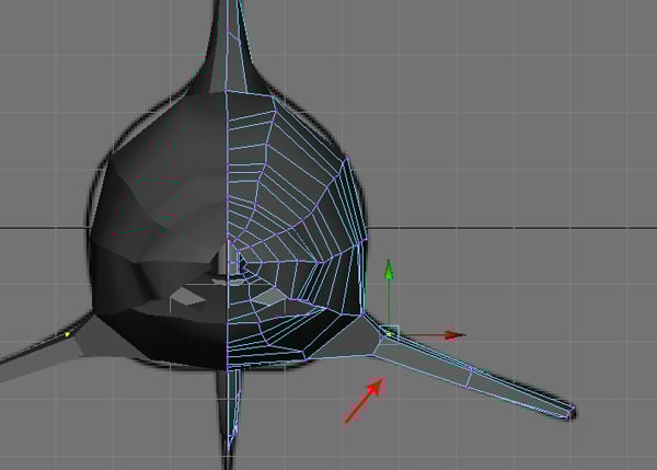
Now we will make the pelvic fin of the shark. Select the bottom face around the pelvic fin area according to the reference image.
Step 13
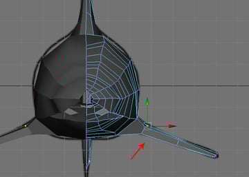
And Extrude the selected face once.
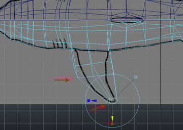
Head back to the Perspective view, and properly arrange the vertices of the pelvic fin.

Also jump into the Top view, and then try to maintain the shape according to the top reference image.
Step 14
Now we will make the pectoral fins of the shark. Select the two bottom faces around the pectoral fin area following their placement on the reference image.
Step 15
With the faces selected, go to Edit Mesh and select the Extrude tool.

Step 16
In the Top view, Extrude the faces two times as shown.
Step 17
Also try to arrange the vertices according to the reference image.
Step 18
To make the fin curved, we need to add several edge loops. Again go to the Edit Mesh menu, and then select the Insert Edge Loop Tool.

Step 19
Here I have inserted one edge loop, and then arranged the vertices according to reference.

Step 20
Next, jump in the Front view and then try to match the fin’s outline to the reference image.
5. Creating the Nose & Mouth
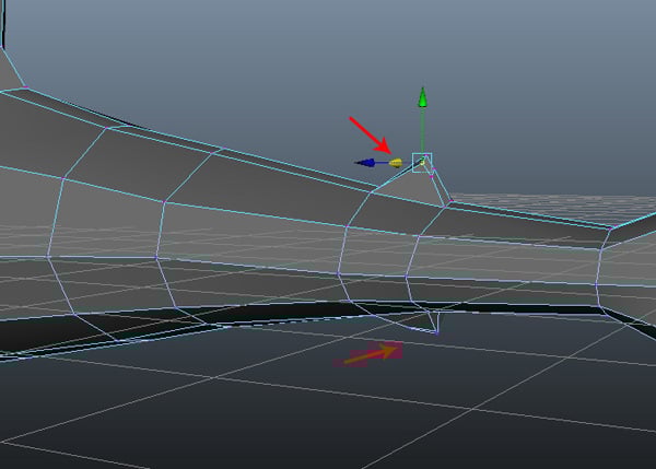
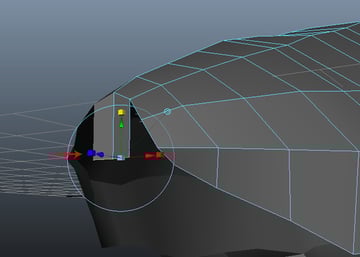
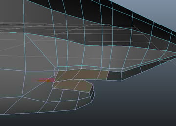
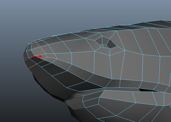
Step 1
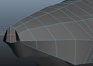
Now we'll work on the tip of the nose. Select the edge of the nostril and then Extrude it once, as shown in the image.

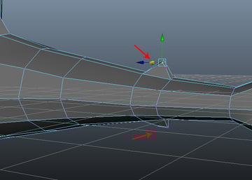
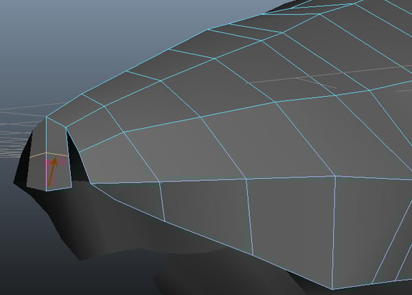
Step 2
With the help of the Insert Edge Loop Tool, insert one edge between the extruded faces as shown.
Step 3
Now select the two corresponding vertices and go to the Edit Mesh menu, and choose Merge.

Step 4
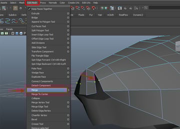
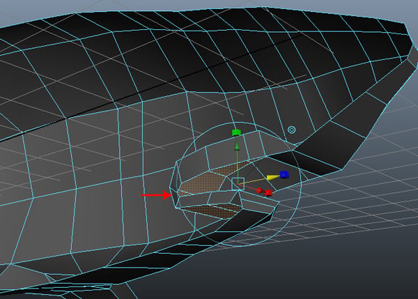
Using this method, complete the merging operation on the remaining pair of verts. Now select the eight boarder edges.

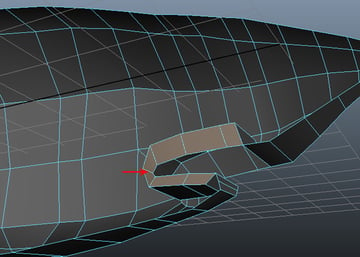
Step 5
With the edges selected, Extrude them once towards the inside to fill the gap.

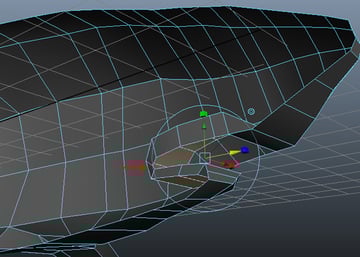
Step 6
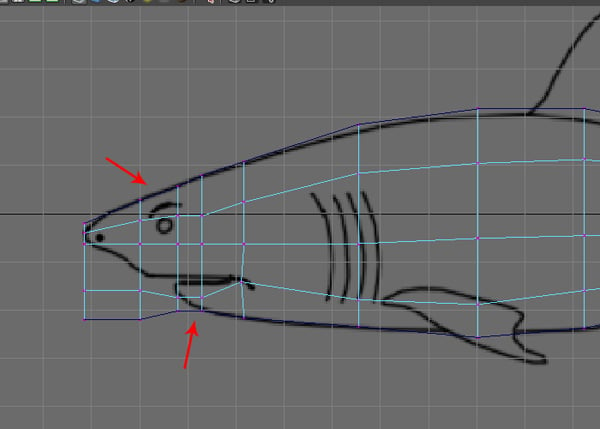
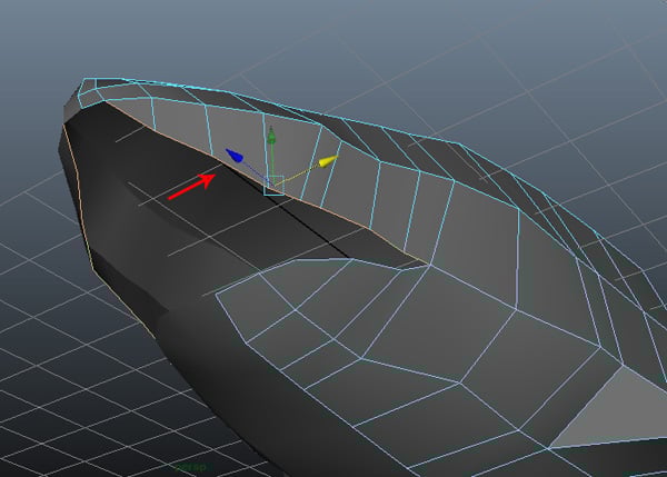
We'll do the same thing for the lower jaw. Select the three edges of the lower jaw, as shown in the image.
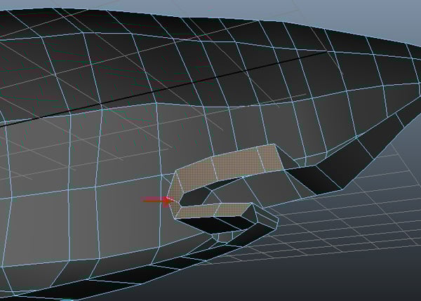
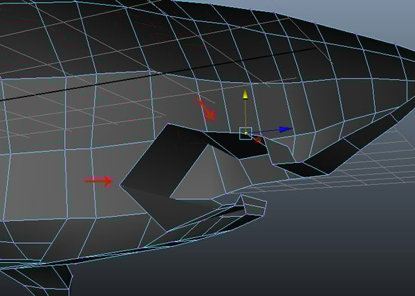
Step 7
With the lower jaw edges selected, Extrude these inside the same as we did with the upper jaw’s edges.

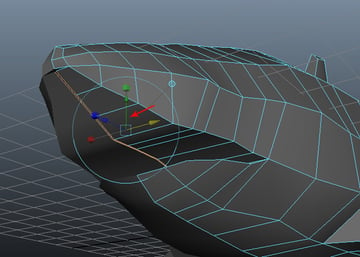
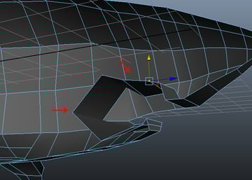
Step 8
Now let’s isolate half of the shark body. So with exactly half of the shark body selected, go to the Show menu (in the menu bar), and then check on the View Selected check box, from inside the Isolate Select submenu.

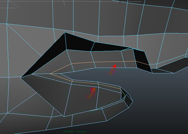
Step 9
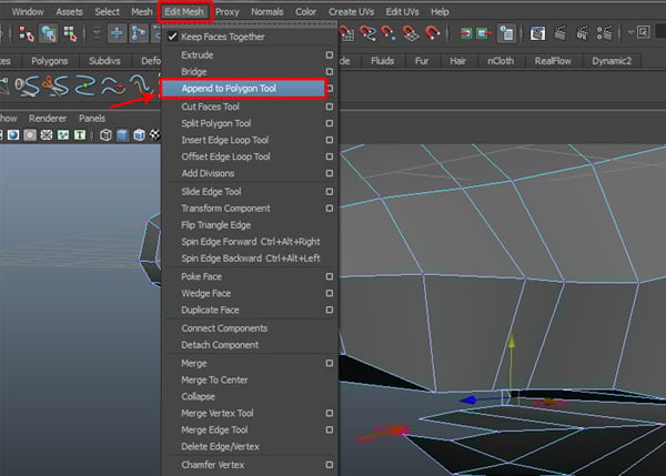
Now go to the Edit Mesh menu and select the Append to Polygon Tool.
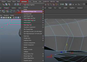
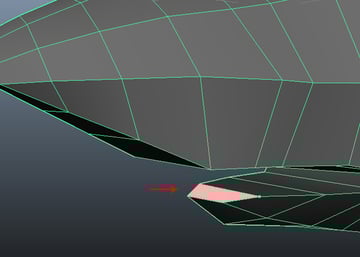
With the Append to Polygon Tool selected, click on the parallel border edges to create a face to fill the gap. Then press Enter to apply and finish with the Append to Polygon Tool.

Step 10
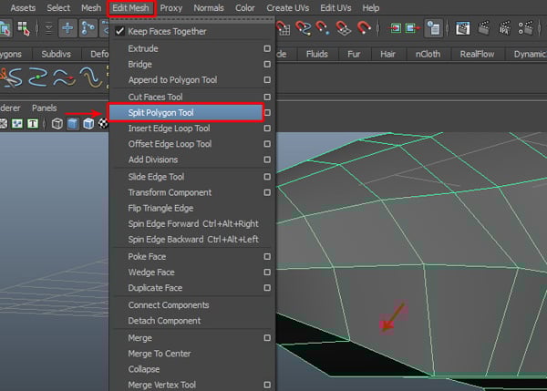
Now we need to split some faces to add more detail. Go to the Edit Mesh menu and select the Split Polygon Tool.
Step 11
With the Split Polygon Tool selected, split the mouth border faces as shown in the image below.

Also split the corner faces, to eliminate the triangulated faces.

Step 12
Now, select the faces inside the mouth.
With the inner mouth polygons selected, Extrude them once, as shown in the image.
Step 13
After extruding the faces, select the unneeded border faces (as shown in the image.) and Delete them.
Step 14
After deleting the faces, press F9 for Vertex selection mode and then arrange the vertices to form a gap inside the mouth.
Step 15
Also insert an extra edge loop with the Insert Edge Loop Tool, as shown in the image.

Step 16
We have now completed the blocking of the shark mesh. Now we can convert it into Subdiv mode to add more details, or we can convert it later after completing the modeling of the eyes and nostrils.

6. Refining the Head
Step 1
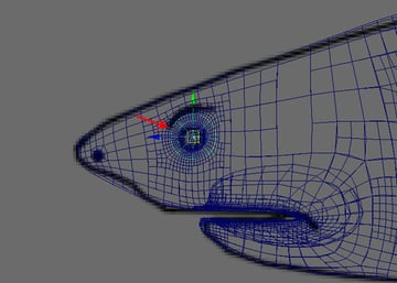
In this case, we will complete the eye and nose parts first, and then convert it to subdivision later, to add extra detail with sculpting. Select the two faces around the eye area, and then Extrude them inwards to make the eye socket.
Step 2
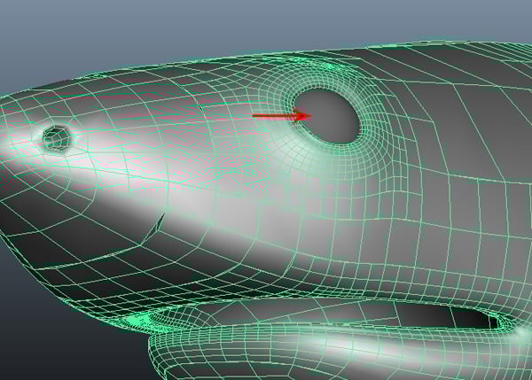
Also add an edge loop to make the nose hole, as shown in the image below.

Step 3
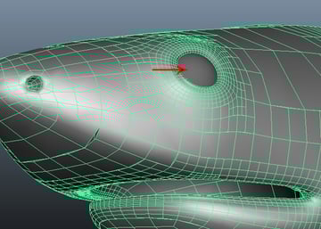
We'll do the same thing for the nostrils as well.
Step 4
Select the two faces around the nostril area, and Extrude them inwards to make a hole.

7. Adding the Gills
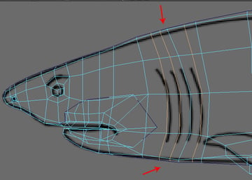
Step 1
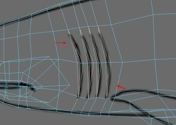
Now we'll make the gill slits for the shark. With the help of the Insert Edge Loop Tool, insert three edge loops around the gill area, according to the reference image.

Step 2
Using the Split Polygon Tool, split each gill slit edge to add more detail.

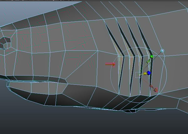
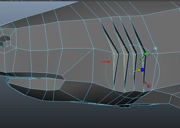
Step 3
Now press F11 for Face selection mode, and with all the split faces selected, Extrude them inside to create a cavity.
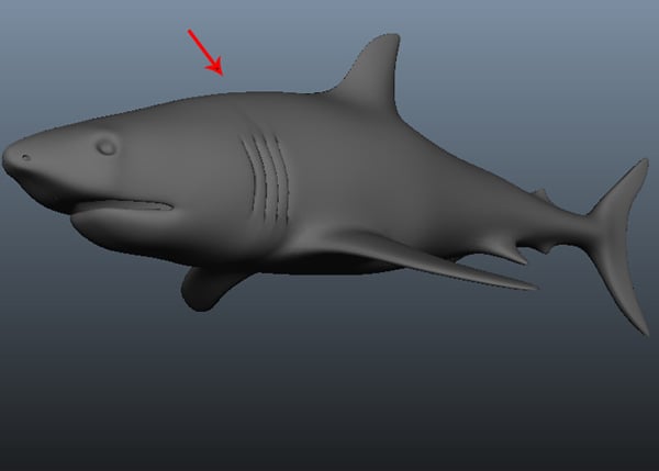
Step 4
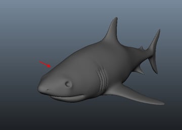
We have now completed the base model of the shark. But we still need to add more detail to it.

8. Combining Meshes
Step 1
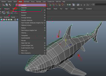
Now we'll use subdivision conversion to do sculpting and detailed modeling. First select both side meshes, and then go to the Mesh menu and choose Combine, to attach the selected polygon meshes together.

Step 2
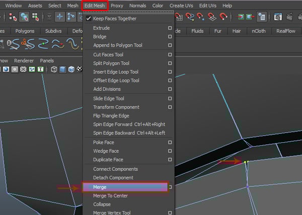
Now select a pair of border vertices along the center, and then go to the Edit Mesh menu and select Merge, to weld the selected vertices.
Step 3
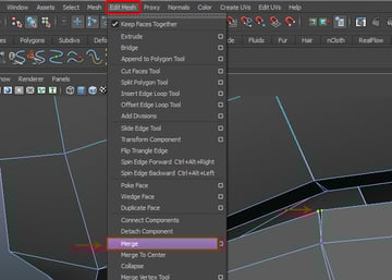
In this way, select and Merge all the center border vertices one by one.

9. Initial UVs
Step 1
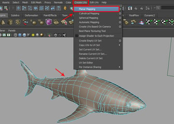
Before converting from polygon to a subdivision surface, we need to apply UV mapping for texturing. With half of the shark body mesh selected, go to the Create UVs menu, and click on the Planar Mapping options box.
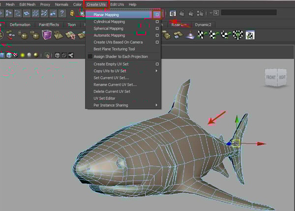
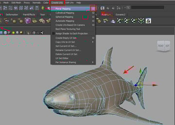
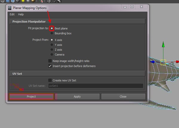
In the Planar Mapping Options box, turn on the Fit projection: Best Plane radio button, as shown in the image below.
Step 2
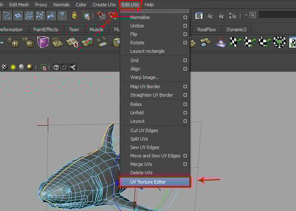
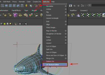
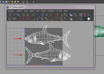
After applying a planar map, go to the Edit UVs menu and select UV Texture Editor to see the UV map.
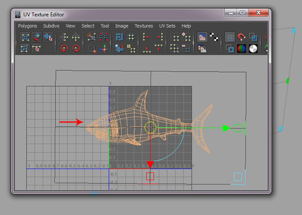
You can see the result of the applied planar map from a side view of the shark body mesh.
Step 3
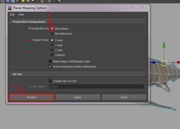
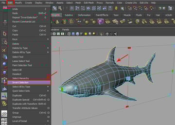
To apply the planar map to the other side, first select the half with the applied planar map, and then go to the Edit menu and select Invert Selection.

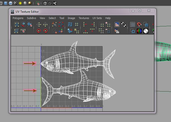
With the other side’s faces selected, go to Create UVs and select Planar Mapping.

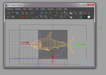
You can see the result in the UVs Texture editor window. We will edit it later.
10. Mesh Cleanup
Step 1
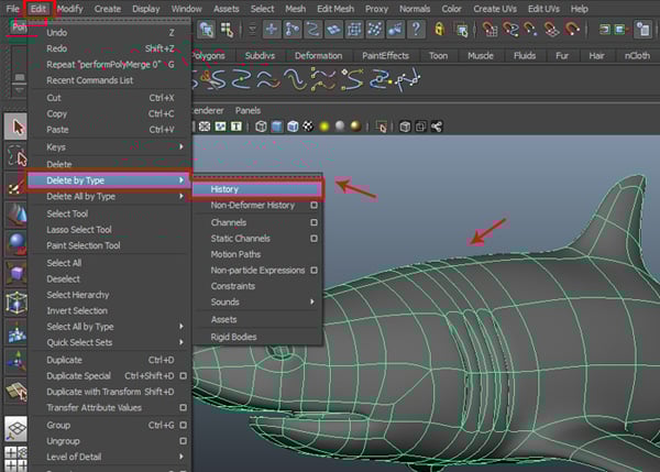
Now with the shark body mesh selected, go to the Edit menu and select History, from inside the Delete by Type submenu to delete the history.

Step 2
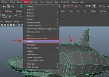
Now go to the Mesh menu and select Cleanup.

Step 3
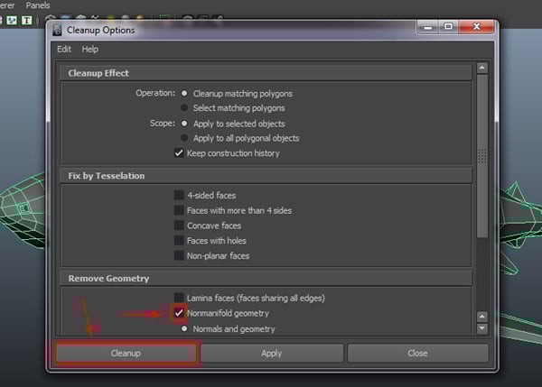
In the Cleanup Options window, check on the Nonmanifold geometry option and then click on the Cleanup button, to clean up the selected polygon mesh.

11. Converting to Subdivision
Step 1
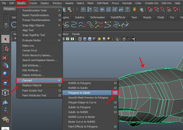
After this, select the shark mesh and go to the Modify menu and click on the Polygon to Subdiv option box, from inside the Convert submenu.

Step 2
In the Convert NURBS/Polygon to Subdiv Options window, keep the Maximum base mesh faces value at 10000, and then click on the Create button.
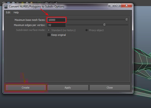

When we convert a polygon mesh to a subdivision surface, it may delete its shader node. In this case, we may need to apply the shader node again.
Step 3
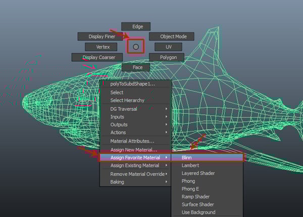
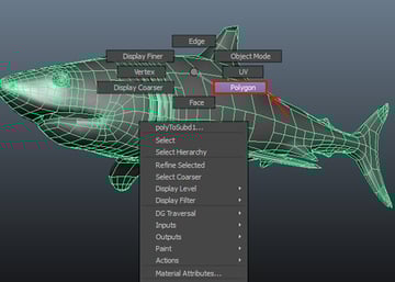
With the shark polygon mesh selected, Right Click in the viewport and select Blinn from inside the Assign Favorite Material fly-out menu.

Step 4
Once again, you can see the surface shader has been applied to the selected shark mesh.

Step 5
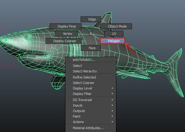
With the shark body selected, Right Click and hold, and then choose the Polygon option.
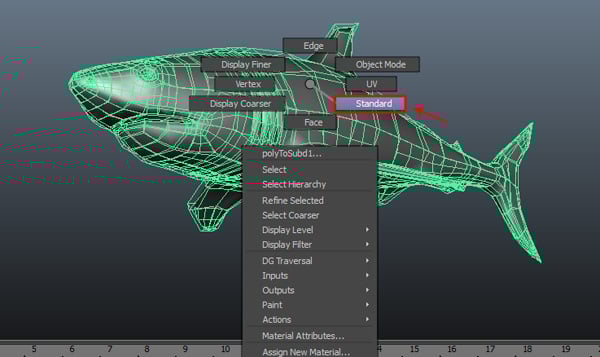
Step 6
Again, Right Click on the shark body and choose Standard mode. You'll see some changes in the Standard mode; therefore we can always interchange between both Standard and Polygon mode to use their tools as needed. So, here we have selected Standard mode to use subdivision tools.

Step 7
Again Right Click and select Vertex mode, to select the vertices.
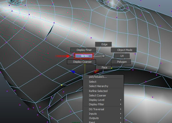

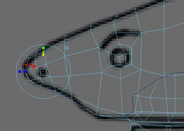
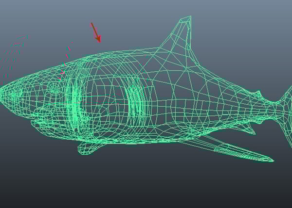
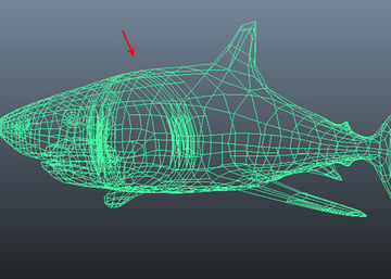
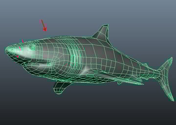
Again do a Right Click and select Display Finer, to display the finer components,s as shown in the image below.
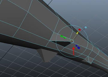
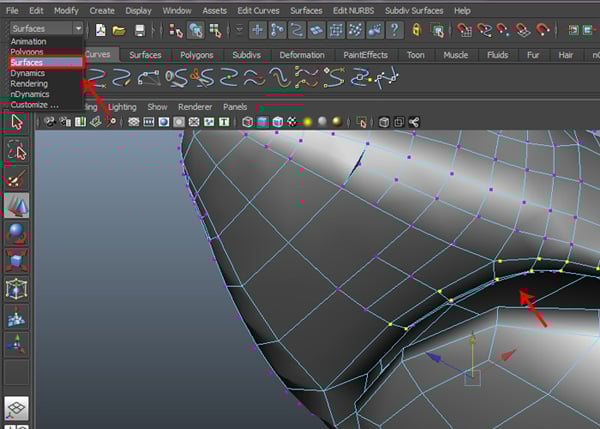
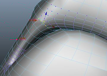
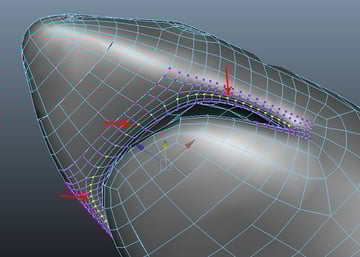
Step 8
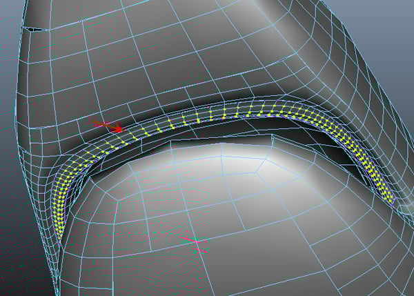
After this, you'll see the finer vertices close to the subdivision surface as control vertices. Now select some vertices around the lip outline and then change the mode to Surface, as shown in the image below.
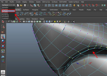
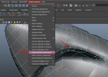
Step 9
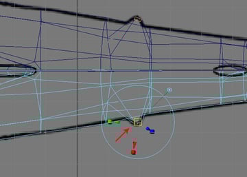
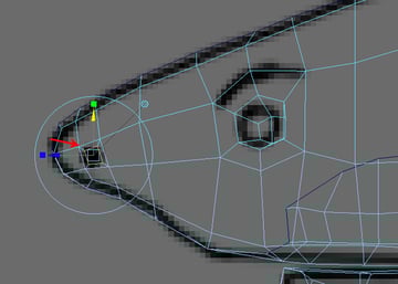
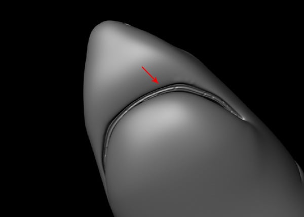
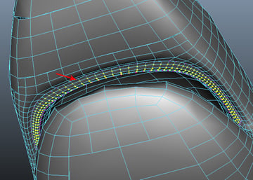
With the same vertices selected, go to the Subdiv Surfaces menu and select Refine Selected Components.
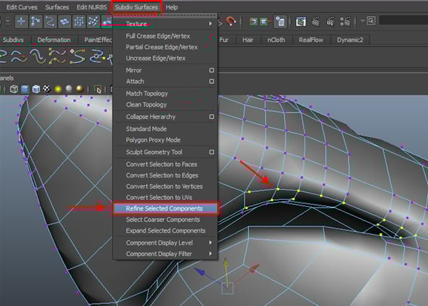
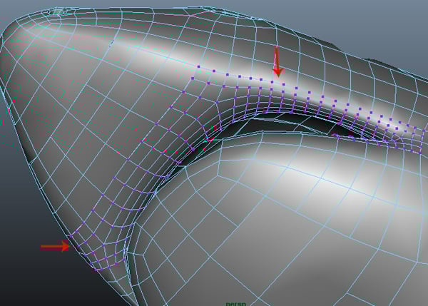
You can see some changes after using the Refine Selected Components command. Now you can arrange the vertices or sculpt the area as you need.
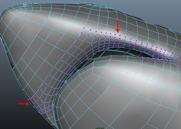
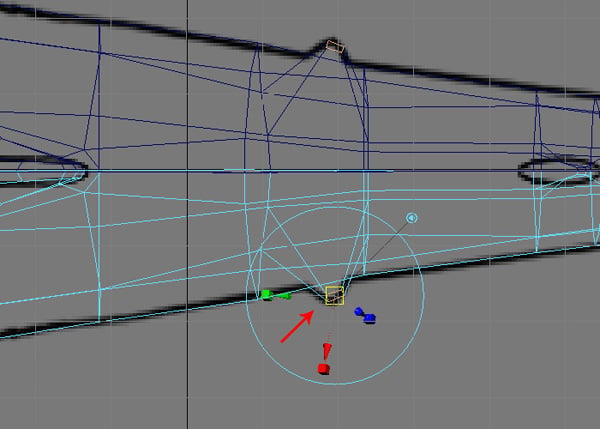
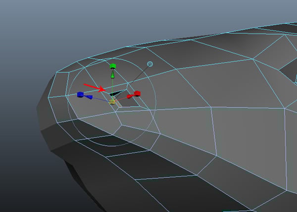
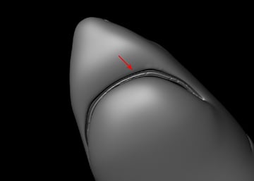
Step 10
Now you may notice that several vertices are not displayed properly. After selecting those vertices, try to adjust them a bit so you can see the finer vertices, as shown in the image below.

12. Adding Detail to the Mouth
Step 1
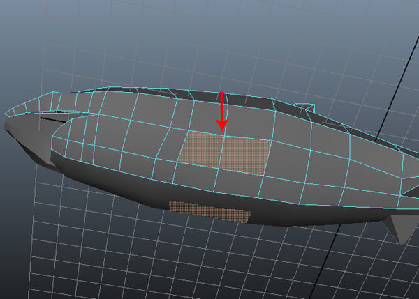
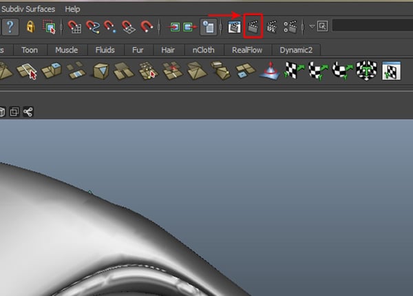
Now select a row of vertices around the lip outline and move them up a bit.

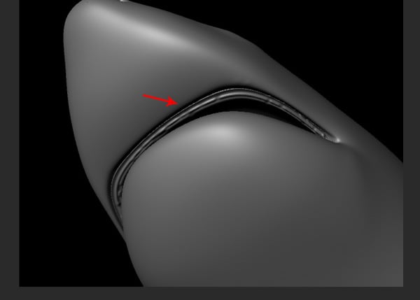
If you want to check to see how it look, just click on the Current Render Frame button on the main tool bar.
You can then see the result in a rendered frame. Moving the row of the vertices, has made a space for the teeth and gums.

Step 2
Just like this, keep arranging the vertices to sculpt the mesh as you need, and to add more detail.
It will take a bit of time and your own creativity for you to come up with the teeth and gums space.

13. Creating & Positioning the Teeth
Step 1
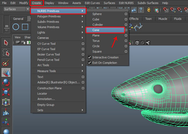
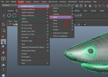
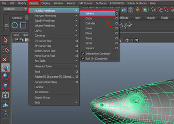
Now it’s time to create the teeth for the shark. Go to the Create menu and select the Cone tool, from inside the NURBS Primitives submenu.
Step 2
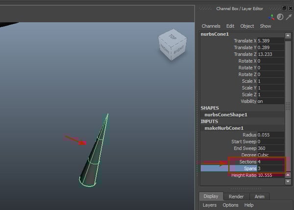
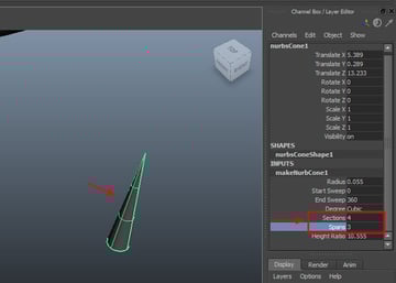
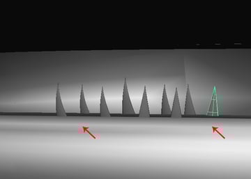
Now draw a cone shape in the viewport with the following values: Sections: 4, Span: 3. And also don’t forget to delete the bottom cap face.
Step 3
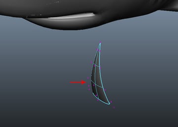
With the cone mesh selected, press F9 to enter Vertex selection mode and then arrange the vertices to form a shark’s tooth.

Step 4
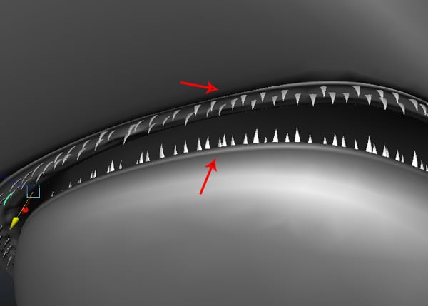
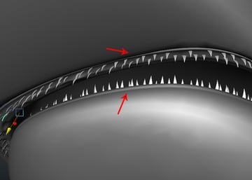
Make several copies of the tooth mesh and distribute them with random scale values onto the lower and upper gum areas.

Step 5
We are now done with the teeth arrangement.
14. Creating the Eyes
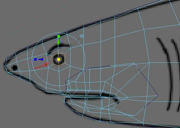
Step 1
Everything is almost complete, except for the eyes. Go to the Create menu and select Sphere, from inside the NURBS Primitives menu.
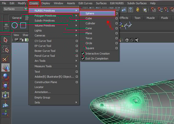
Jump into the Side view and draw a Sphere around the eye area, as shown in the background image.

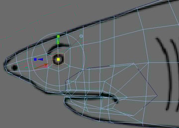
Step 2
Finally position the sphere properly, so it looks like an eyeball.
Conclusion
Finally, we have completed the modeling of the shark. In the next part of the tutorial, we'll learn about proper unwrapping and texturing. I hope you enjoyed this part.


 By
By


