
1. Modelling the Eyes
Step 1
Open the project file which you had saved in the last part of the tutorial. In the side view, navigate to Create > NURBS Primitives > Sphere command. Then draw a sphere in the viewport and put it around the eye area.
.jpg)
.jpg)
Step 2
With the sphere selected, navigate to the Channel Editor and set the End Sweep value as 346.249. The value may differ in your case. This option turns the sphere into an opened eye shape. Change the Section value to 10 and Spans value to 5.
.jpg)
.jpg)
Step 3
With the NURBS sphere selected, navigate to Modify > Convert and click on NURBS to Polygon option box.
.jpg)
.jpg)
Step 4
This opens the Convert NURBS to Polygon Options box. From here, turn on Control Points radio button and then click on Tessellate button to apply this command.
.jpg)
.jpg)
Step 5
Now, the NURBS sphere is converted into a polygon. The base NURBS sphere remains in the same place.
.jpg)
.jpg)
The Polygonal Sphere
You don't need the base NURBS sphere. So, with the base NURBS sphere selected, press Delete command to delete that.
.jpg)
.jpg)
Step 6
With the sphere selected, go to Show > Isolate Select and then turn on View Selected check box to isolate it.
.jpg)
.jpg)
Step 7
Now, press F11 key to jump into face selection mode and then select and delete the indicated back faces as shown in the following image.
.jpg)
.jpg)
Then turn off View Selected check box to unhide the hidden objects.
.jpg)
.jpg)
Step 8
Next, first select the body mesh and then with Shift key pressed, select the eye mesh. Then go to Mesh > Combine command to attach the selected meshes together.
.jpg)
.jpg)
Step 9
After combining the meshes, you need to merge the vertices. Navigate to Edit Mesh menu and select Merge Vertex Tool.
.jpg)
.jpg)
With the Merge Vertex Tool selected, select the corresponding vertices and merge them together.
.jpg)
.jpg)
Step 10
With the help of Insert Edge Loop Tool, insert several edge loops according to the mesh topology. In this way, you have completed the eyelids.
.jpg)
.jpg)
2. Modelling the Tongue
Step 1
Create a polygonal box primitive with Height, Width and Depth subdivision values as 2 and place it inside the mouth of the parrot.
.jpg)
.jpg)
Step 2
Select and delete the half faces of the box. With the rest part of the box selected, go to Edit > Duplicate Special.
.jpg)
.jpg)
Step 3
After duplicating the box polygon mesh, select its both sides and then go to Show menu in the panel menu bar and then select Isolate Select and turn on View Selected check box to isolate the selected objects.
.jpg)
.jpg)
Step 4
Being in the vertex selection mode, edit the vertices to form the shape like the tongue.
.jpg)
.jpg)
Step 5
To add smoothness to the tongue mesh, you need to increase the subdivisions. With the tongue mesh selected, go to Mesh > Smooth command to smooth the selected mesh.
.jpg)
.jpg)
Smoothing the Tongue
.jpg)
.jpg)
Step 6
After smoothing the tongue mesh, edit the tongue shape as shown in the following image.
.jpg)
.jpg)
3. Modelling the Throat
Step 1
In this step you will model the throat. Navigate to Create > NURBS Primitives > Cone.
.jpg)
.jpg)
Create a cone shape on the grid with the values of Spans as 4 and Sections as 8.
.jpg)
.jpg)
Step 2
Put this cone inside the mouth and around the throat area. With the cone surface object selected, right click and select Control Vertex option to edit it in the vertex selection mode.
.jpg)
.jpg)
Edit the vertices of the throat mesh to form the shape as shown in the following image.
.jpg)
.jpg)
4. Joining Meshes
Step 1
Unhide the opposite side of the body. With both sides’ meshes selected, go to Mesh > Combine command to attach the selected meshes together.
.jpg)
.jpg)
Step 2
After combining the meshes, turn on vertex selection mode and then select both sides’ border vertices. Navigate to Edit Mesh > Merge command to merge the selected vertices together.
.jpg)
.jpg)
5. Modelling Feathers
Step 1
Now you will start modelling the feathers. Create a plane polygon primitive with the values of Height subdivisions as 5 and Width subdivision as 2. In the vertex selection mode, edit the vertices to form the shape as shown in the following image.
.jpg)
.jpg)
Step 2
Make a duplicate copy of the feather mesh. Delete the two row’s faces of the duplicate mesh and place it over the previous feather mesh.
.jpg)
.jpg)
Step 3
Make two more copies of the feather and place them as shown in the following image.
.jpg)
.jpg)
Step 4
With all three feathers selected, go to Edit > Group command to group the selected feathers together.
.jpg)
.jpg)
Step 5
With the group of the feathers selected, go to Modify > Center Pivot to place the pivot to the center.
.jpg)
.jpg)
Step 6
With the D key pressed, move the pivot in Z axis to the starting point of the feathers as shown in the following image.
.jpg)
.jpg)
Step 7
Make a duplicate entity of the grouped mesh and scale it in Y axis to flip in the opposite side.
.jpg)
.jpg)
With both feathers group selected, group them together.
.jpg)
.jpg)
Step 8
Make a copy of the feather group and place it beneath the arm of the parrot as shown in the following image.
.jpg)
.jpg)
Placing the Feathers
Following the same process, create three more copies of the feather and place them at the different joint bends as shown in the following image. Scale them accordingly, too.
.jpg)
.jpg)
Step 9
In this way,
you have arranged the feathers like this.
.jpg)
.jpg)
Arranging the Feathers
Do same with the opposite side, as well.
.jpg)
.jpg)
Step 10
Following the same process, make the tail feathers also.
.jpg)
.jpg)
Step 11
Make the crown feathers also as shown in the following image.
.jpg)
.jpg)
Step 12
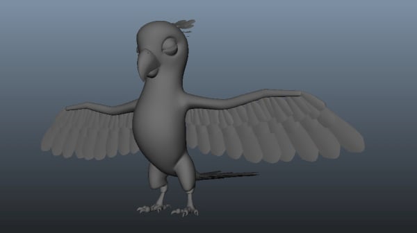
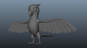
You can see the result in the shaded mode what you have created so far.
.jpg)
.jpg)
6. Unwrapping the Body Mesh
Step 1
The next step is unwrapping. With the body mesh selected, navigate to Show menu in panel menu bar, select Isolate Select and then turn on View Selected check box.
.jpg)
.jpg)
Step 2
With the body mesh selected, go to Edit UVs > UV Texture Editor command.
.jpg)
.jpg)
Step 3
It opens the UV Texture Editor window. The UV structure looks quite messy. So, you have to unwrap it properly as per the requirement.
.jpg)
.jpg)
Step 4
You will unwrap the shells part wise. With the body mesh selected, navigate to Create UVs > Planar Mapping command.
.jpg)
.jpg)
After applying the Planar Mapping command, you will see something similar to this in the UVs Editor window.
.jpg)
.jpg)
Step 5
Now, you will make separate shells for unwrapping. In the edge selection mode, double click on neck edge loop for loop selection. With the loop selected, go to Polygon > Cut UV Edges in UVs Editor window.
.jpg)
.jpg)
Step 6
After cutting the shell, turn on face selection mode by pressing F11 key and select any face inside the shell area. With the face selected, go to Select > Select Shell command in UVs Editor window.
.jpg)
.jpg)
After applying Select Shell command, you can see separate shell created in the UV Editor.
.jpg)
.jpg)
Step 7
Next, with both arms edge loops selected, navigate to Polygons > Cut UV Edges.
.jpg)
.jpg)
Now select both arms’ shells just like you did in an earlier step.
.jpg)
.jpg)
Step 8
In the same way, you have selected the legs’ shells.
.jpg)
.jpg)
And the torso part, also.
.jpg)
.jpg)
7. Applying Map in Head Shell
Step 1
With the head mesh shell selected, go to Create UVs > Spherical Mapping.
.jpg)
.jpg)
Step 2
After applying the Spherical Mapping, the head shell gets unwrapped. Though this is not relaxed and unfolded properly. You need to unfold and relax the UVs.
.jpg)
.jpg)
Step 3
Select the UVs by pressing F12 key and then navigate to Polygons > Unfold command to unfold selected UVs shell.
.jpg)
.jpg)
Step 4
After applying the Unfold command, you can see the eye area UVs is still not unfolded properly. Select the eyes’ UVs and then navigate to Polygons > Relax option box to open its settings window.
.jpg)
.jpg)
In the Relax UVs Options window, check the Pin UVs option, turn on Pin unselected UVs radio button and then keep Maximum iterations value as 1 and then click on Relax button.
.jpg)
.jpg)
Step 5
In this way, you have unwrapped the head shell UVs properly.
.jpg)
.jpg)
8. Applying Map in Body Shell
Step 1
With the torso shell selected, navigate to Create UVs > Cylinder Mapping tool to apply the cylindrical map.
.jpg)
.jpg)
After applying the Cylinder Mapping tool, the torso shell gets unwrapped. But it looks quite messy. You will follow the same procedure as you did with head UVs.
.jpg)
.jpg)
Step 2
After using Unfold and Relax tools, the torso UVs gets unwrapped quite properly.
.jpg)
.jpg)
9. Joining Head and Body Shells
Step 1
In this part of the process you need to join the head and the torso UVs together. Put both UVs nearby each other. You may need to scale the UVs to match the size mutually.
.jpg)
.jpg)
Step 2
Press F10 key for edge selection mode and then select the border edge loops which you need to sew. Then navigate to Polygons > Move and Sew UV Edges command in the UV Texture Editor.
.jpg)
.jpg)
Step 3
The head and the body UVs are connected in one shell. You can also tweak the UVs in UVs selection mode.
.jpg)
.jpg)
10. Applying Map in Thigh Shell
Step 1
Now, you will unwrap the parrot’s thighs. With the left side thigh shell selected, navigate to Create UVs > Cylinder Mapping tool.
.jpg)
.jpg)
Step 2
After applying the Cylinder Mapping tool, select the entire UVs shell in the UV Texture Editor window and then go to Tool > Smooth UV Tool.
.jpg)
.jpg)
Step 3
After applying the Smooth UV Tool, you will see a small menu inside the UV Texture Editor window. In this menu, click and slide the left mouse button on the Unfold button. You will see the UVs being unfolded.
.jpg)
.jpg)
Step 4
Now, you have to attach or sew the gap area. So, with the open edges selected, navigate to Polygons > Sew UV Edges tool.
.jpg)
.jpg)
Step 5
In this way, you have edited both sides’ thigh’s shells by using tools and manually editing.
.jpg)
.jpg)
11. Applying Map in Arm Shell
Step 1
Now, you will unwrap the parrot’s hands. With the left side’s hand’s shell selected, navigate to Create UVs > Cylinder Mapping tool.
.jpg)
.jpg)
You can see the UVs in the UV Texture Editor window. This is a closed UVs shell, so you need to divide it in two parts.
.jpg)
.jpg)
Step 2
Press F10 key for edge selection mode and then select the edge loop as shown in the following image.
.jpg)
.jpg)
Then navigate to Polygons > Cut UV Edges tool in UV Texture Editor.
.jpg)
.jpg)
Step 3
Next, apply Planar Map just like you did previously. It should now look like the following image.
.jpg)
.jpg)
Step 4
Select the border edge loop of any of the shells and then navigate to Polygons > Move and Sew UV Edges command.
.jpg)
.jpg)
Step 5
After using Move and Sew UV Edges command, navigate to Tool > Smooth UV Tool. Then slide and drag the Unfold and Relax buttons on Smooth UV Tool.
.jpg)
.jpg)
Step 6
In this way, you have unwrapped both sides’ hands UVs.
.jpg)
.jpg)
Step 7
After unwrapping the upper body parts, arrange the UVs layout as shown in UV Texture Editor window.
.jpg)
.jpg)
12. Unwrapping Legs
Step 1
You will need to unwrap the parrot’s legs. With the leg selected, navigate to Show > Isolate Select and then check on View Selected to make it isolated.
.jpg)
.jpg)
Step 2
In the edge selection mode, select the indicated edge loop as shown in the following image. Then navigate to Edit UVs and select Cut UV Edges.
.jpg)
.jpg)
Step 3
After using Cut UV Edges tool, select the entire shell and then navigate to Create UVs > Cylinder Mapping.
.jpg)
.jpg)
After applying the Cylinder Mapping, you can see unwrapped UVs inside the UV Texture Editor window. This is however not opened properly.
.jpg)
.jpg)
Step 4
So, apply Smooth UV Tool just like you did previously. After editing the UVs, you will see something like this.
.jpg)
.jpg)
Step 5
Next, select the edge loops as shown in the following image. Then navigate to Edit UVs > Cut UV Edges tool to divide the shell.
.jpg)
.jpg)
Step 6
Next, select the bottom shell and then go to Create UVs > Planar Mapping.
.jpg)
.jpg)
After applying the Planar Mapping, it should look like following image.
.jpg)
.jpg)
Step 7
After unfolding and relaxing the UVs, it will look like this.
.jpg)
.jpg)
Step 8
Following the same way, with the upper shell selected, navigate to Create UVs > Planar Mapping.
.jpg)
.jpg)
Step 9
In this way, you have edited and unwrapped the foot and claws as shown in the following image.
.jpg)
.jpg)
13. Unwrapping Nails
Step 1
Now you’ll unwrap the nails. So, with the nails selected, navigate to Show > Isolate Select and then turn on View Selected check box.
.jpg)
.jpg)
Step 2
In the edge selection mode, select the center edge loop of all nails. Then navigate to Edit UVs > Cut UV Edges.
.jpg)
.jpg)
Step 3
With the one side shell selected of the nail, navigate to Create UVs > Planar Mapping.
.jpg)
.jpg)
After applying the Planar Mapping command, you can see result in the UV Texture Editor window.
.jpg)
.jpg)
Step 4
In this way, you have edited both sides’ nails’ UVs and relaxed them properly as shown in the following image.
.jpg)
.jpg)
Step 5
In this way, you have completed all nails UVs as shown in UV Texture Editor window.
.jpg)
.jpg)
Step 6
After unwrapping the entire leg parts’ UVs, arrange them in the UV Editor as shown in the following image.
.jpg)
.jpg)
14. Transferring UV Maps
Step 1
Since you have completed the left leg’s unwrapping, now you need to transfer its UVs map on to the right leg polygon mesh.
.jpg)
.jpg)
Right now, if you check the UVs of the right leg mesh, it looks quite messy.
.jpg)
.jpg)
Step 2
Now, first select the unwrapped left leg and then select the right leg and then go to Mesh > Transfer Attributes option box.
.jpg)
.jpg)
In the Transfer Attributes Options box, turn on Current and Component radio buttons and then click on Transfer button to apply this command.
.jpg)
.jpg)
Step 3
After applying the Transfer command, select the right leg and check its UVs in the UV Texture Editor window. Now, it looks quite perfect.
.jpg)
.jpg)
15. Unwrapping Feathers
Step 1
Now, unwrap the feathers. So turn on the layer visibility button which you had created previously, and then select any of the feathers in the group.
.jpg)
.jpg)
Step 2
After applying, the Planar Map and Relax Tool, you can see the unwrapped UVs of the feather in the UV Texture Editor window.
.jpg)
.jpg)
Step 3
Once you have unwrapped a feather mesh successfully, just transfer its UVs to the rest of the feathers also using Transfer Attribute command just like you did previously.
.jpg)
.jpg)
Step 4
In this way, you have completed the unwraping of all parts of the parrot. In the next part of the tutorial, I will show you how to implement texturing.
.jpg)
.jpg)
Conclusion
In this tutorial I have shown you how to how to model the eye, tongue, throat and feathers of a parrot. In the next part of the tutorial, I will teach how to unwrap the model for texturing.
 By
By


