
1. Creating a UV Map for the Base Plate
Step 1
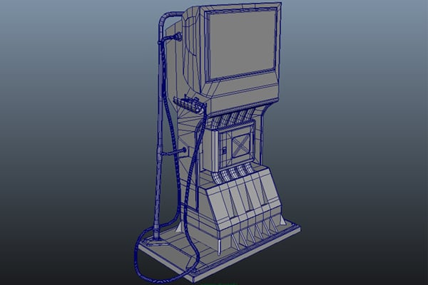
Open the fuel pump file in Maya which was saved in the previous part of the tutorial.


Step 2
Select
the base plate polymesh of the fuel pump.


Step 3
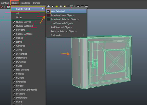
Go to Show > Isolate Selected > View Selected command and check on its option box. The base plate gets isolated.


Step 4
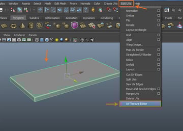
With the base plate selected, go to Edit UVs > UV Texture Editor command.

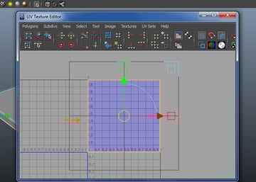
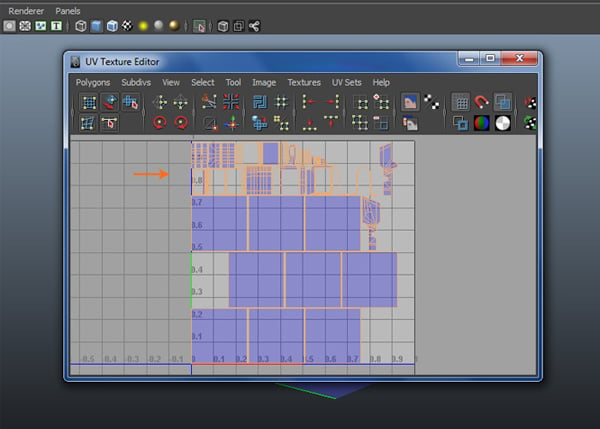
Step 5
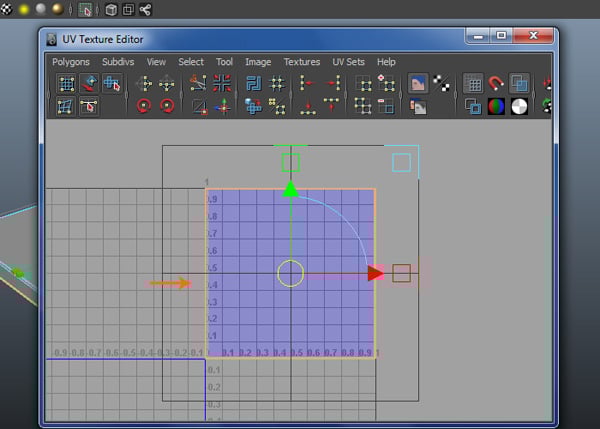
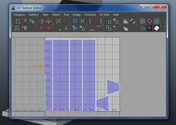
In the UV Texture Editor window, you can see the default UVs map layout as shown in the following image.


Step 6
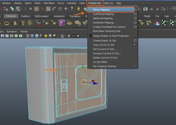
With the base plate polymesh selected, go to CreateUVs > Planar Mapping and click on its option box.


Step 7
In the Planar Mapping Options window, turn on Fit projection to Best Plane radio button and click on Project button to apply the planar mapping command.


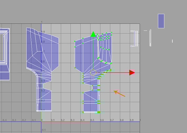
Step 8
After applying the planar mapping command, the planar mapping gizmo appears on the polymesh. It can be adjusted according to the need.


You can see the applied planar mapping inside the UV Texture Editor window.
Step 9
Right-click inside the UV Texture Editor window and select UV component.


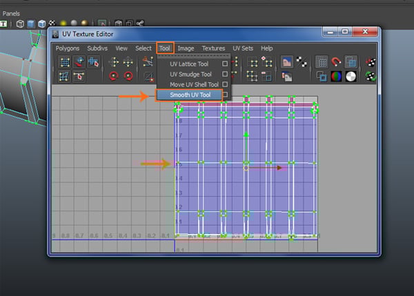
Step 10
With UVs selected, go to Tool > Smooth UV Tool and click on its options box to open the Smooth UV Tool.


Step 11
In the Smooth UV Tool Options window, check on Pin Borders option and click on Apply and Close button.


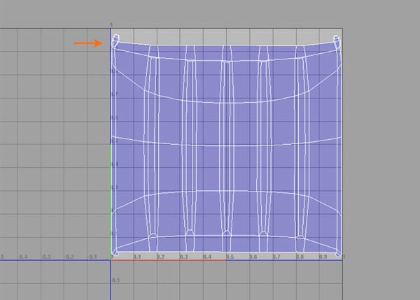
Step 12
Now the Smooth UV Tool options are visible. Click and drag the mouse button horizontally on Unfold and Relax. In this way, the UVs mapping of the base plate polymesh is completed.


2. Unwrapping the Base Stand Plate
Step 1
With the base stand plate polymesh selected, go to Show > Isolate Select and turn on View selected command to isolate the selected polymesh.


Step 2
Being in the face selection mode, select the top surface faces of the base stand plate. Go to Create UVs > Planar Mapping.


Step 3
Inside the UV Texture Editor window, select and drag the top faces UVs out of the UVs layout area.


Step 4
Select the side faces of the base stand plate.


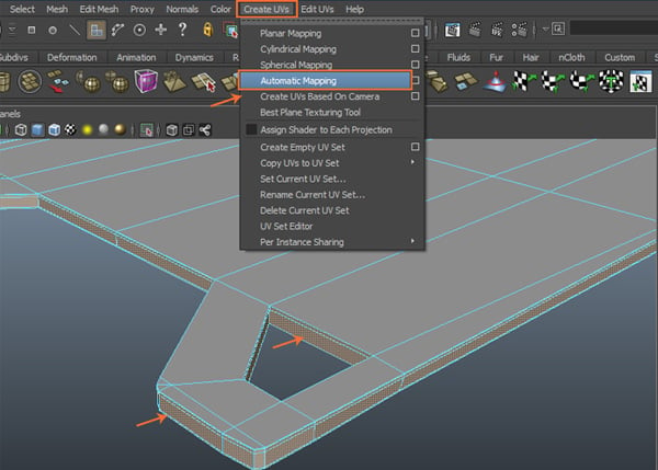
Step 5
Go to Create UVs > Automatic Mapping command.

Step 6
You can see the result of Automatic Mapping inside the UV Texture Editor window.


Step 7
Arrange all extracted UVs shells inside the UV layout area.


3. Unwrapping the Motor Chamber's Cover Case
Step 1
Next, isolate the motor chamber cover base. With the motor chamber cover case selected, go to Create UVs > Automatic Mapping command.


Step 2
You can see that all UVs are arranged automatically inside the UV editor. The unwrapping of the motor chamber cover base polygon mesh has been completed.


4. Unwrapping the Support Meshes
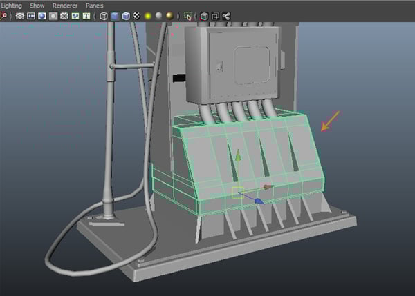
Step 1
Select and isolate the support meshes.


Step 2
With the support meshes selected, go to Create UVs > Automatic Mapping command.


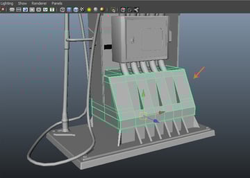
Step 3
After applying the Automatic Mapping command, you can see the projections and transform gizmo to adjust the UVs inside the viewport.


You can see the result inside the UV Texture Editor window. All UVs Shells are arranged properly inside the UV layout.


5. Unwrapping the Motor Chamber
Step 1
Select and isolate the motor chamber.
Step 2
After isolating the motor chamber, select and delete the unwanted side and bottom faces.


Step 3
With the motor chamber mesh selected, go to Create UVs > Automatic Mapping command.


Step 4
You can see the result inside the UV Texture Editor window.


6. Unwrapping the Pipe Controller Box
Step 1
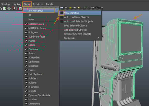
With the pipe controller box polymesh selected, go to Show > Isolate Selected and check on View Selected command to isolate the selected object.

Step 2
With the entire surface faces selected, go to Create UVs > Automatic Mapping command.


Step 3
You can see the unwrapped UVs inside the UV Texture Editor.


Step 4
Invert the face selection mode to select the cover poly mesh. Go to Create UVs > Planar Mapping.

Step 5
In this way, you have unwrapped the pipe controller box polygon mesh. Now, you have to attach the distracted UVs according to the polygon shape by using Sew UV Edges command.


Step 6
For using Sew UV Edges command, you have to select the edges inside the UV Texture Editor. So, being in the edge selection mode, select an edge. After selecting an edge, its mutual corresponding edge which you would attach it with, would be highlighted automatically.


Step 7
With the corresponding edges selected, go to Polygon > Move and Sew UV Edges command inside the UV Texture Editor window.


Both UVs are attached now.


Step 8
In this way, you have to attach multiple UVs to form a complete unwrapped and boxed shape as shown in the following image.


Step 9
In the same way, you have to attach the gapped UVs. So, with the corresponding edges selected, go to Polygon > UV Texture Editor > Move and Sew UV Edges.


Step 10
After completing the unwrapping of the pipe controller box, arrange the UVs layout as shown in the following image.


7. Unwrapping the Dial Case
Step 1
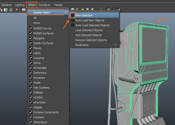
With the dial case mesh selected, go to Show > Isolate Select and turn on View Selected check box to isolate the selected object.
Step 2
With the dial case mesh selected, go to Create UVs > Automatic Mapping command.


Step 3
You can see the result inside the UV Texture Editor window.

Step 4
With the inner border edges selected, go to Polygon > Move and Sew UV Edges command.


Step 5
This is what you would get after sewing the extracted UVs.


Step 6
In this way, you have completed the back side projection UVs as shown in the following image.


Step 7
Following the same way, complete the other side’s UVs also.


Step 8
With the back side’s faces selected, go to Create UVs > Planar Mapping command.


Step 9
Following the unwrapping method stated in the earlier steps, unwrap and sew the UVs of the back faces.

Step 10
Scale down the UVs and fit them inside the layout area.


8. Unwrapping the Under Section Pipe Channel
Step 1
With all section pipes selected, go to Mesh > Combine command to attach all selected pipes together.


Step 2
Isolate the pipes. With the faces of the pipes selected, go to Create UVs > Planar Mapping command.


Step 3
You get the unwrapped UVs of the pipes as shown in the following image.


Step 4
With the same faces selected, go to Edit > Invert Selection command to invert the selection.


Step 5
With the inverted faces selected, go to Create UVs > Planar Mapping command.


Step 6
In this way, the unwrapping of under section pipe channel is completed.


9. Unwrapping the Fuel Hand Pump Holder
Step 1
With the fuel hand pump holder polygon mesh selected, go to Create UVs > Planar Mapping command.


Step 2
You can see the fuel hand pump holder’s UVs inside the UV Texture Editor window. Go to Tool > Smooth UV Tool command.

Step 3
After applying Smooth UV Tool command, you get Unfold and Relax sliding options. Use both commands to unfold and relax the UVs.


Step 4
To unfold a particular folded UV, go to Polygon > Unfold command to unfold the selected folded UVs as shown in the following image.


Step 5
In this way, the unwrapping of the fuel hand pump holder is completed. You can see the result in the following image.

10. Unwrapping the Pipe Connector Chamber Box
Step 1
With the pipe connector chamber box polygon mesh selected, go to Create UVs > Automatic Mapping command.


Step 2
Following the same way, complete the unwrapping of the pipe connector chamber box. You can see the unwrapped UVs layout in the following image.

11. Unwrapping the Hand Pump
Step 1
With the hand pump polygon mesh selected, go to Show > Isolate Select > View Selected and turn on its option box to isolate the selected object.


Step 2
With the hand pump model polygon mesh selected, press F10 key for edge selection mode. Double-click on the middle edge to select the edge loop.


With the edge loop selected, go to Edit UVs > Cut UV Edges command to split the mesh in half.


Step 3
With any of the faces selected, go to Select > Select Shell command in the UV Texture Editor window.


Step 4
With one side’s faces selected, go to Create UVs > Planar Mapping.


Step 5
With planar mapping applied on both sides’ shells, you can see the UVs layout in the UV Texture Editor window.


Step 6
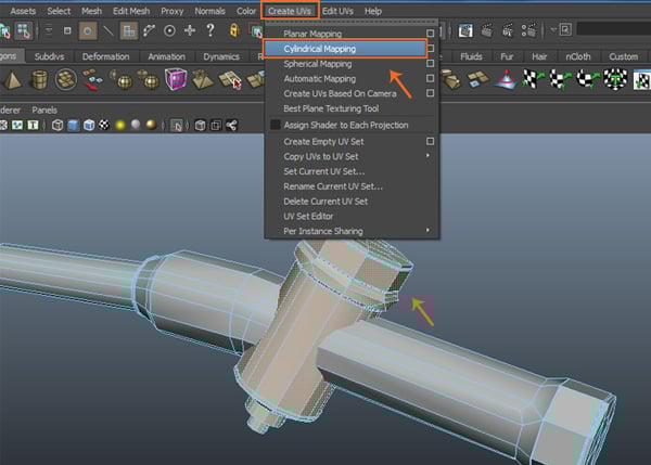
With rest of the fuel controller chamber mesh selected, go to Create UVs > Cylindrical Mapping command.

Step 7
After applying the cylindrical mapping, adjust the UVs in the UV Texture Editor window.


Step 8
It’s time to sew the seams of the UVs. Being in the edge selection mode, select any two corresponding edges and go to Polygons > Move and Sew UV Edges command.


Step 9
After sewing the UVs, arrange it in the layout area inside the UVs Texture Editor window.


12. Unwrapping the Handle and Trigger
Step 1
Isolate the handle and trigger polygon meshes.


Step 2
Following the previous method, select the faces of the handle and trigger and apply planar mapping. Arrange the UVs properly inside the layout area of the UV Texture Editor window.


13. Unwrapping the Nut and Bolt
Step 1
With all four nut bolt meshes selected, combine them together. Apply planar mapping on the top faces and cylindrical mapping on the side faces.


Step 2
In this way, the unwrapping of all bolts is done. Arrange them all inside the UV Texture Editor properly.


14. Unwrapping the Angle Pipe
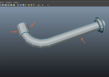
Step 1
Isolate the angle pipe mesh. Select the indicated edge loop of the angle pipe mesh as shown in the following image.

Step 2
Apply cylindrical mapping and arrange the unwrapped UVs in the layout area.


Step 3
In this way, the unwrapping of the entire fuel pump is completed.


Conclusion
In the next part of the tutorial, I'll show you how to apply textures on the unwrapped faces of the fuel pump.
 By
By


