

1. Creating the Under Section Pipes
Step 1
Open the fuel pump file in Maya which was saved in the previous part of the tutorial. To model the pipe channel, create a PolyCylinder with Radius as 0.25, Height as 5, Subdivision Axis as 12 and Subdivisions Height as 10.


Step 2
Press F9 key for the vertex selection mode. Select the indicated vertices and arrange them as shown in the following image.


Step 3
Switch to the Animation mode to get animation tools.


Step 4
With all upper vertices selected, go to Create Deformers > Nonlinear > Bend command.


Step 5
With the poly cylinder object selected in viewport, go to the Channel Box/ Layer Editor and select bend1 in INPUTS section.


Step 6
Change the values of Curvature to 1.2 and Low Bound to 0.


Step 7
With the PolyCylinder selected, go to Edit > Delete by Type > History command to delete history.


Step 8
Follow the same technique to bend the bottom of the pipe. Keep the values of Curvature as 1.2 and Low Bound as 0.


Step 9
Put the pipe at the empty channel place as shown in the following image.


Step 10
Make four copies of the same pipe and distribute them all as shown in the following image. Keep some distance between each section pipe.


1. Creating the Pipe Control Box
Step 1
Create a small box with PolyCube.


Step 2
Create a cylinder with Subdivisions Axis as 14 and Subdivisions Cap as 2.


Step 3
Press F11 key for the face selection mode. Select and delete the back face of the PolyCube.


Step 4
Put the box inside the channel box as shown in the following image.
Step 5
With both corner edges of the box selected, go to Edit Mesh > Bevel and click on its option box.


Step 6
In the Bevel Options window, keep the Width as 0.2500 and Segments as 2. Click on Bevel button to apply the command.


Step 7
Following the same procedure, apply Bevel effect on to the top and bottom edges also.


Step 8
With the channel box and pipes selected, go to Show > Isolate Select > and turn on View Selected option.


Step 9
With the back faces of the pipe selected, press Delete button to delete the faces.


Step 10
Do same with all pipes. Removing unwanted center faces of the pipes makes the file light.


3. Adding Details to the Control Box
Step 1
With the center face of the box selected, apply Extrude command and scale it down a bit as shown in the following image.


Step 2
Press G key for repeat the extrude command and push the extruded face back a little bit in Z axis.


Step 3
With the extruded face selected, go to Edit Mesh > Duplicate Face and click on the option box.


Step 4
In the Duplicate Face Options box, check on Separate duplicated faces option and then click on Duplicate button to duplicate the selected face.


Step 5
It separates the face from the main body. You have to add details to make the door of control box.


Step 6
To add details, drag the door plane mesh out and delete the center face of the box mesh.


Step 7
With the door plane mesh selected, insert four edge loops vertically and two edge loops horizontally.


Step 8
With the four indicated vertices selected, go to Edit Mesh > Chamfer Vertex and click on its option box.


Step 9
In the Chamfer Vertex Options box, keep the values of Width as 0.1000 and then click on Chamfer Vertex button.


Step 10
After chamfering the vertices, select the center face and extrude it twice and scale down it a bit to create the border design.


Step 11
With the border faces selected, extrude once.


Step 12
Insert an edge loop in between the extruded face and drag it a little bit out to make a tiny curvature.


Step 13
To make the handle, extrude the indicated face and scale down it a bit as shown in the following image.


Step 14
Add details to the border faces as you did for the door of the cabinet box.


Step 15
Insert two edge loops and extrude the indicated face as shown in the following image.


Step 16
Keep extruding and editing the mesh to create the knob of the cabinet.


Step 17
With the border edges of the cabinet selected, extrude and scale it down a bit.


Step 18
Put the cabinet mesh back to its place.


Step 19
Go to Show > Isolate Select > View Selected and turn off the check box to unhide all elements.


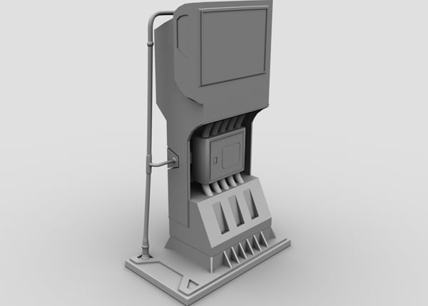
Step 20
This is what you have made so far. In the next part, I will show you how to model the fuel handle, nozzle and pipe.


Conclusion
In the next part of the tutorial, I’ll model the fuel handle, nozzle and pipe.
 By
By


