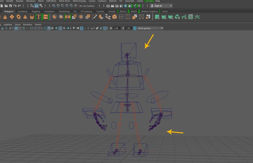
Start Maya and open the file which was saved in the last part of the tutorial.
Start Maya
Step 2
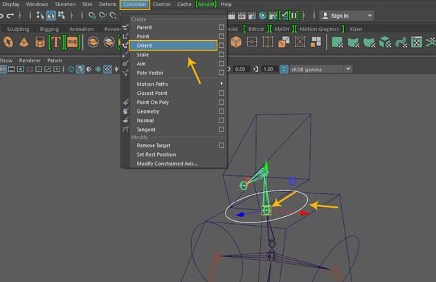
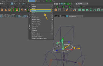
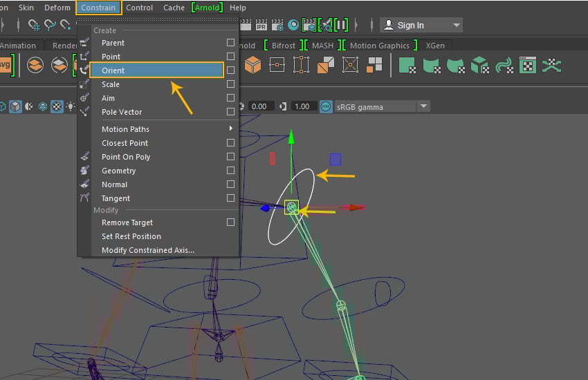
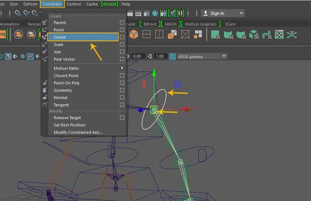
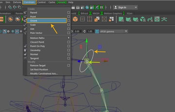
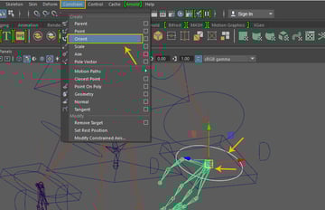
Select Neck_Control followed by Head_Jnt and thengo to Constrain >Orient.
Constrain > Orient
Step 3
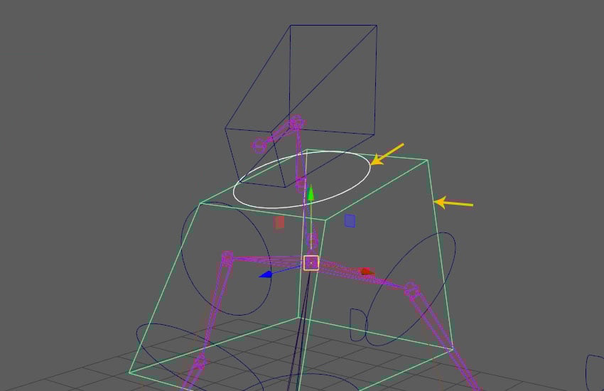
Select Neck_Control followed by Chest_Control and the press P key for creating parent child connection.
Parent child connection
2. Linking Head Controls
Step 1
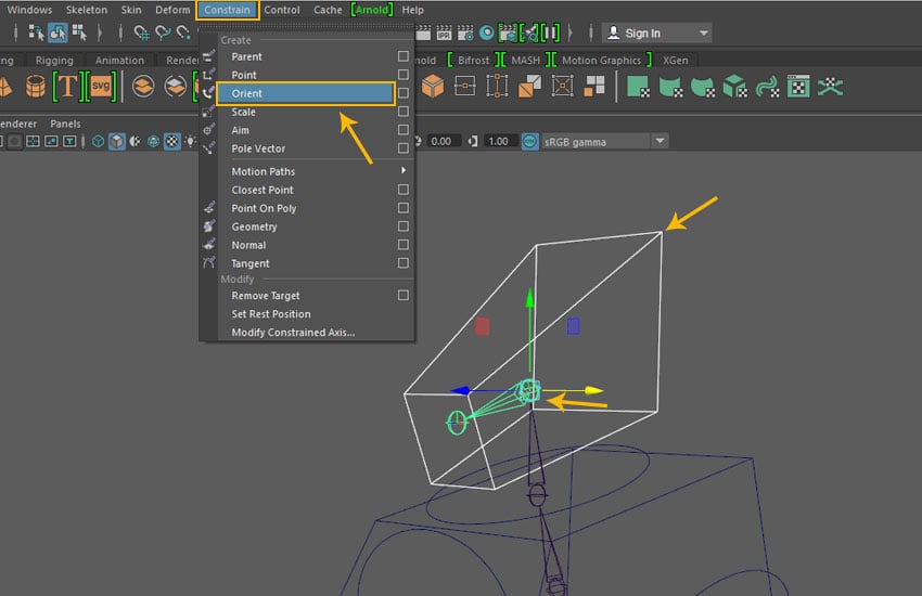
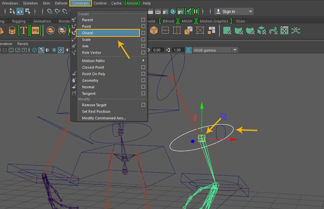
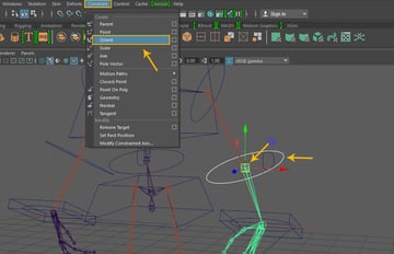
Select Head_Control followed by Head2_Jnt andthengo to Constrain >Orient.
Constrain > Orient
Step 2
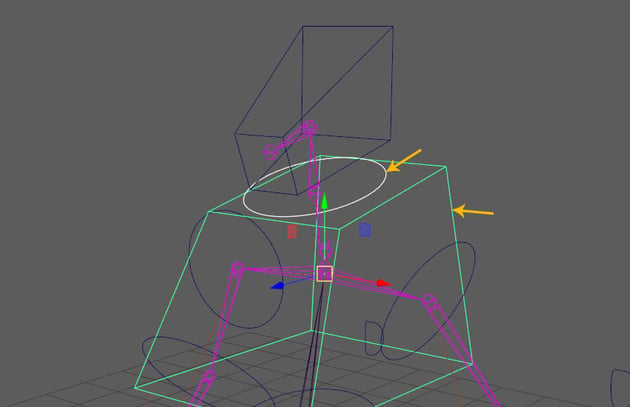
Select Head_Control followed by Neck_Control and then press P key for creating parent child connection.
Parent child connection
3. Linking Hand Controls
Step 1
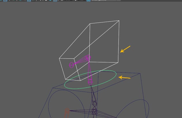
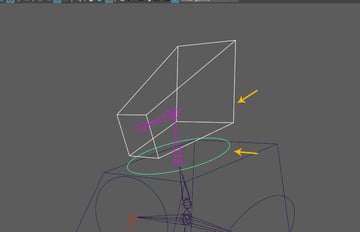
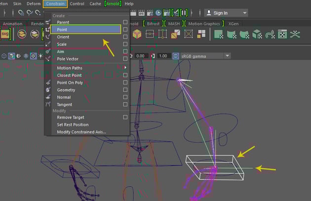
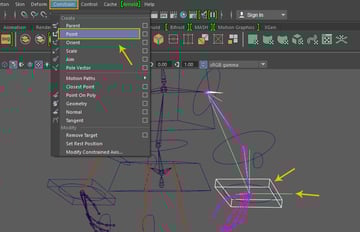
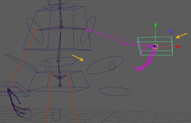
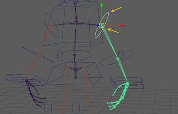
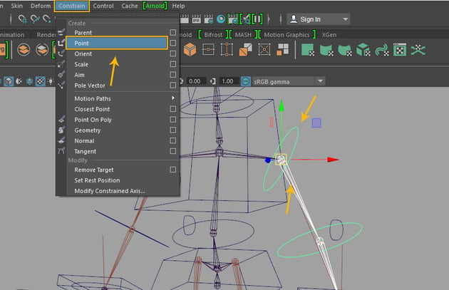
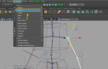
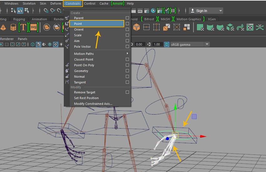
Select Left_Hand_Control followed by Left_Hand_IK_Handle and then go to Constrain >Point.
Constrain > Point
Step 2
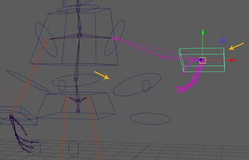
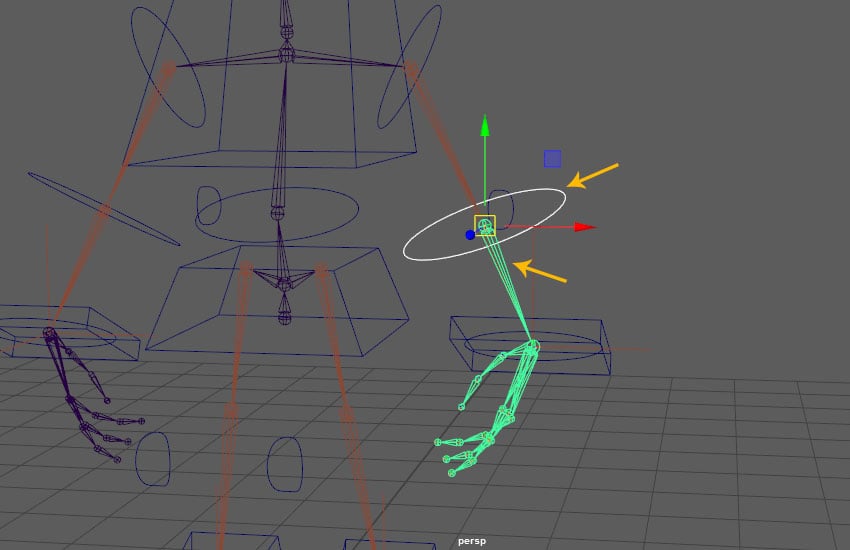
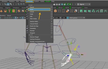
Select Left_Elbow_IK_Control followed by Left_Hand_IK_Handle and thengo to Constrain >Pole Vector.
Constrain > Pole Vector
Step 3
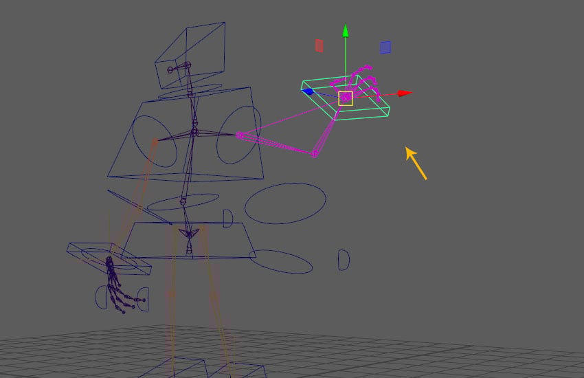
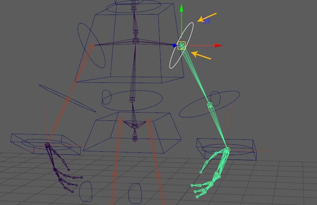
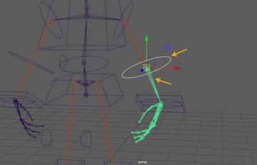
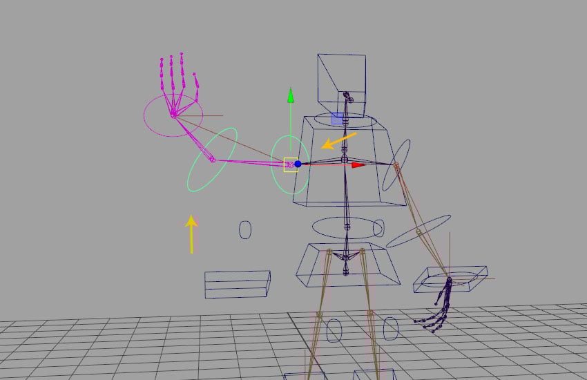
For testing the connection, move the hand control and you will see the hand joints also move according to its movement.
Test the function
4. Linking Head FK Controls
Step 1
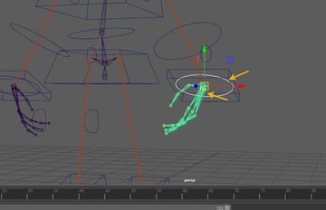
Select Left_Arm_Control followed by Left_Arm_Jnt and then go to Constrain >Orient constrain.
Constrain > Orient constrain
Step 2
Select Left_Elbow_Control followed by Left_Elbow_Jnt and then go to Constrain > Orient constrain. command to apply.
Constrain > Orient constrain
Step 3
Select Left_Wrist_Control followed byLeft_Wrist_Jnt and then go to Constrain >Orient constrain.
Constrain > Orient constrain
Step 4
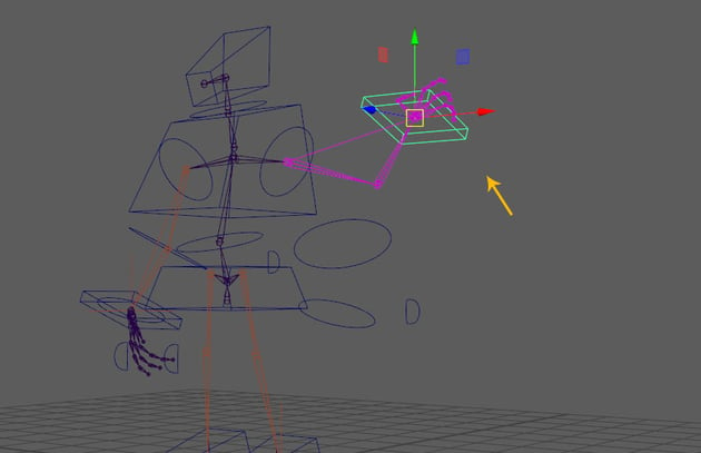
For testing the connection, move the hand control and you will see the FK
controls also move according to that.
Test the function
Step 5
Select Left_Arm_Jnt followed byLeft_Arm_Control and then then go to Constrain >Point constrain.
Constrain > Point constrain
Step 6
Select Left_Elbow_Jnt followed by Left_Elbow_Control and then go to Constrain >Point constrain.
Constrain > Point constrain
Step 7
Select Left_Wrist_Jnt followed by Left_Wrist_Control and then apply Point constrain here too.
Point constrain
Step 8
After connecting above FK hand controls, just move the hand control and you will see the FK
controls also move with other controls.
Test the function
5. Linking Arm, Elbow and Wrist Controls
Step 1
Select Left_Arm_Control followed by Left_Elbow_Control and then press P key for creating parent child relation.
Parent child relation
Step 2
With Left_Wrist_Control selected, press Ctrl-G key to make the group.
Ctrl-G key
Step 3
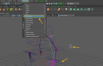
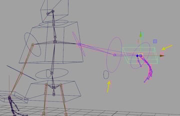
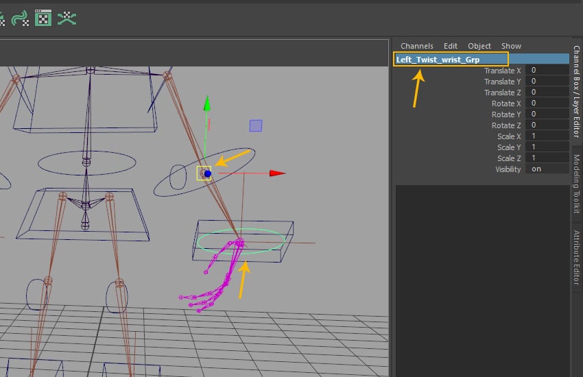
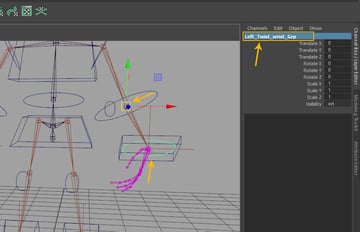
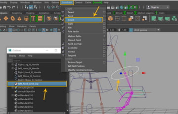
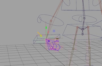
Rename the group as Left_Twist_wrist_Grp
and also snap its pivot with Left_Elbow_Jnt
by pressing D key and dragging the middle mouse button onto Left_Elbow_Jnt as shown in the following image.
Rename the group
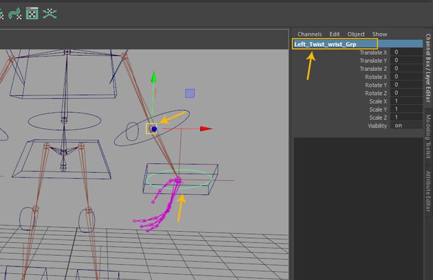
Step 4
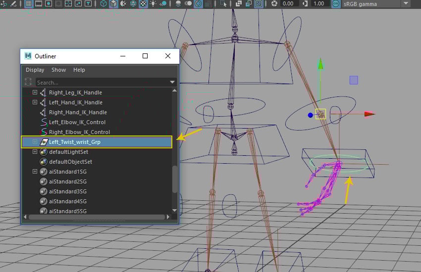
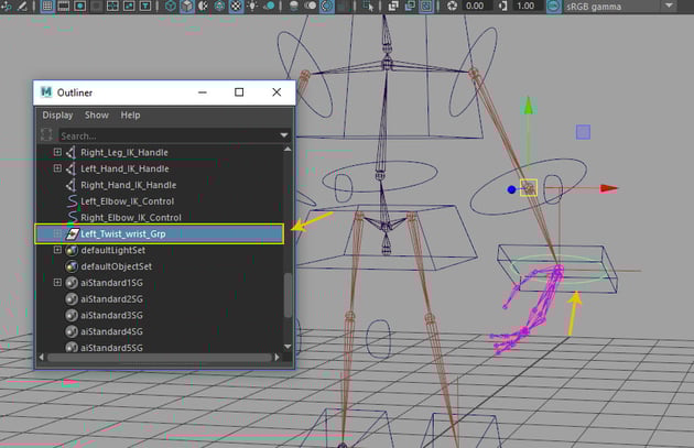
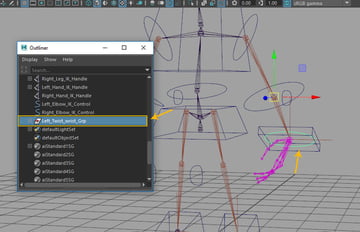
Open Outliner window and you can see the Left_Twist_wrist_Grp in the list as shown in the following image.
Open Outliner window
Step 5
Select Left_Elbow_Control followed by Left_Twist_wrist_Grp and then go to Constrain >Orient constrain.
Constrain > Orient constrain
Step 6
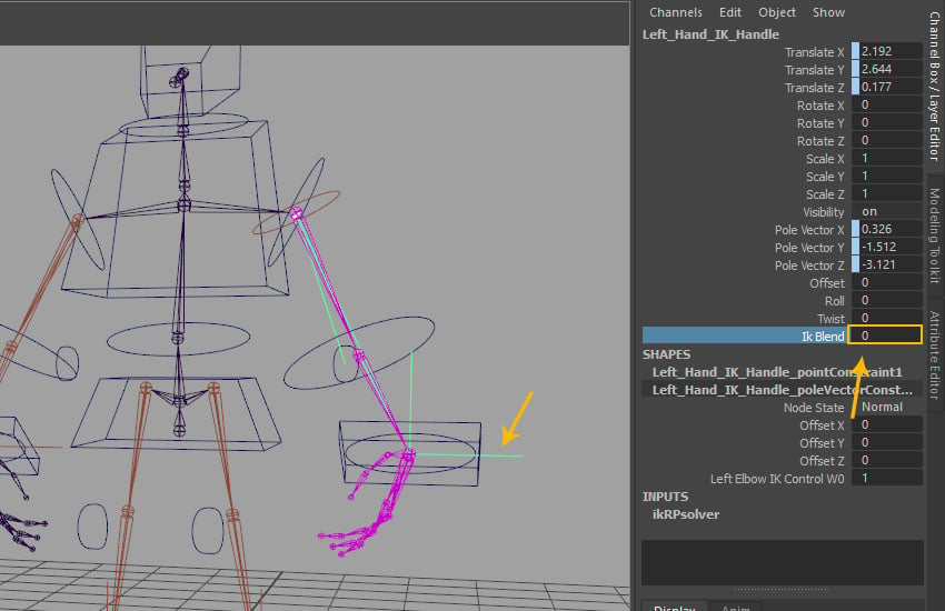
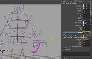
With Left_Hand_IK_Handle selected, go to the channel editor and set the value of Ik Blend to 0 as shown in the following image.
Left_Hand_IK_Handle
Step 7
Select Left_Arm_Jnt followed by Left_Arm_Control and then go to Constrain >Point constrain.
Constrain > Point constrain
Step 8
Select Left_Wrist_Jnt followed by Left_Wrist_Control and then go to Constrain >Point constrain.
Constrain > Point constrain
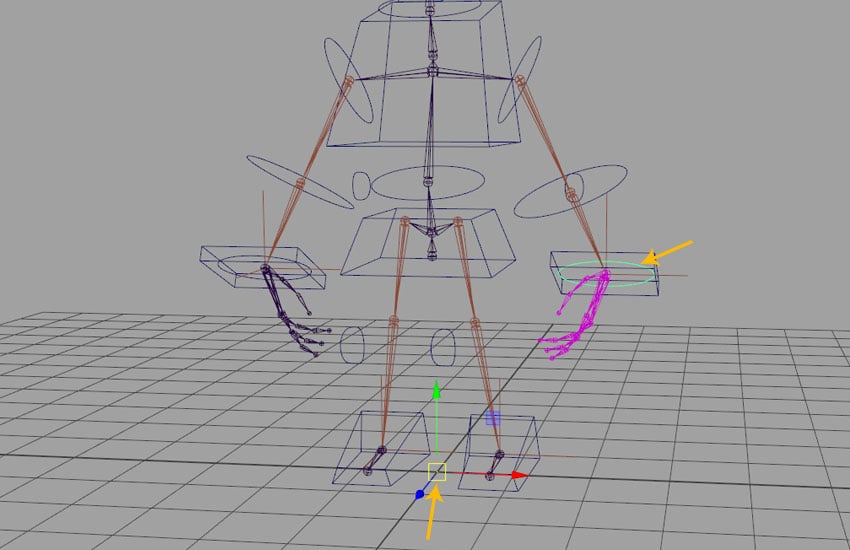
Step 9
Thus, all right hand's controls have been connected well and respectively just like the left hand controls.
Right hand connection done
6. Adding Custom Attributes
Step 1
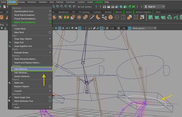
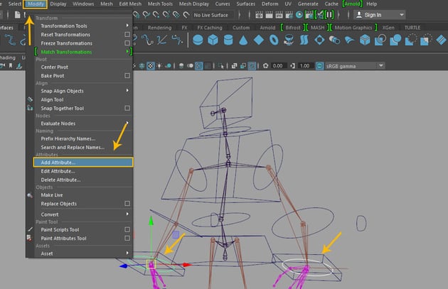
Select Left_Wrist_Control followed by Right_Wrist_Control and then go to Modify >Add Attribute option.
Modify > Add Attribute option
Step 2
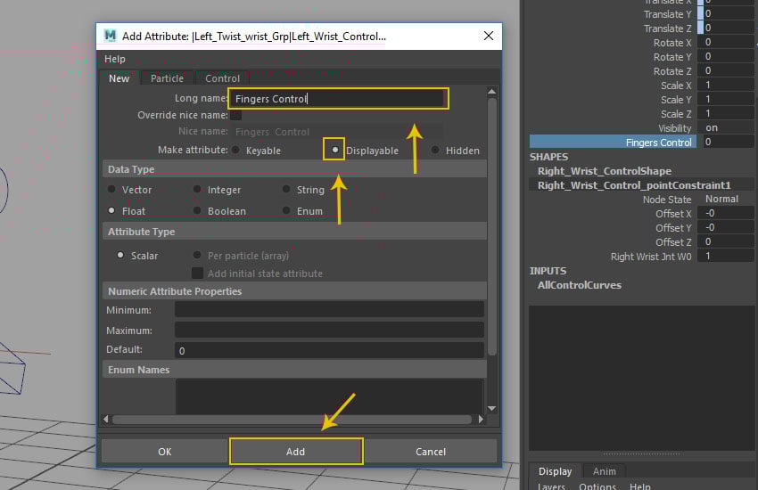
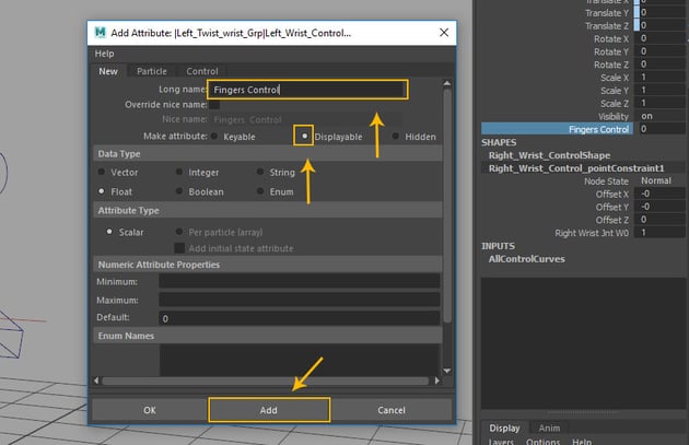
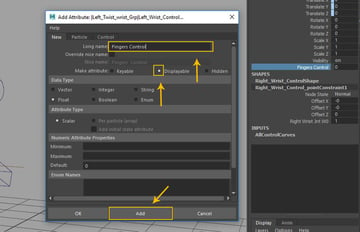
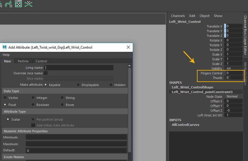
In the Add Attribute window, write Fingers Control in Log name fill box and then turn on Displayable radio button. Click on Add button and you can see the respective attribute created in the channel settings as shown in the following image.
Add Attribute window
Step 3
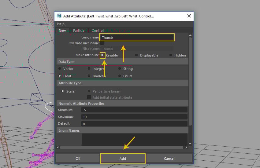
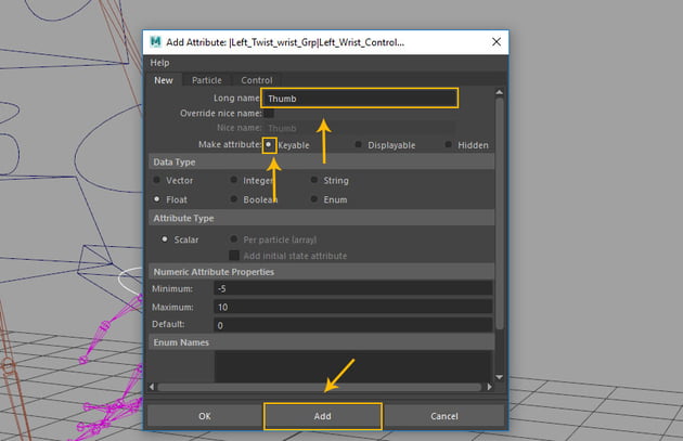
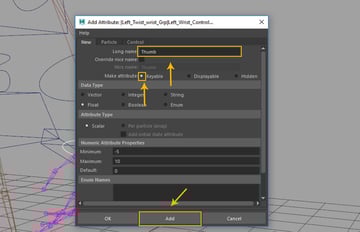
Again in the
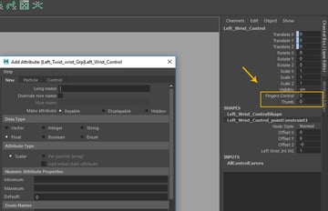
Add Attribute window, write Thumb in Log name fill box and then turn on Keyable radio button. Click on Add button and then you can see the respective attribute created in the channel settings as shown in the following image.
Add Attribute window
Step 4
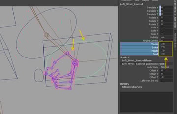
In this way, two types of custom attributes are created in the channel editor as shown in the following image.
Two types of custom attributes
Step 5
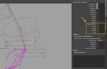
Following the same way, create the custom attributes as Thumb,
Index, Middle and Small fingers
attributes in the channel editor as shown in the following image.
Create the custom attributes
7. Adding Set Driven Key
Step 1
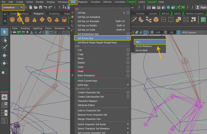
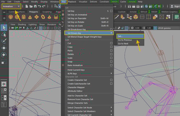
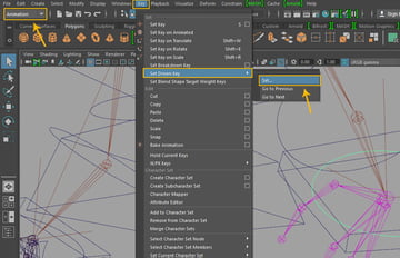
Jump into Animation mode. Go to Key>Set Driven Key>Set command.
Key > Set Driven Key > Set
Step 2
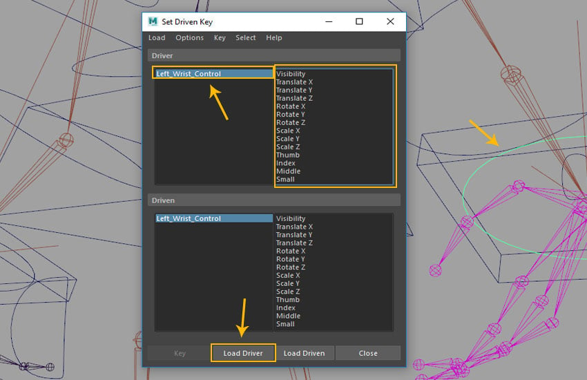
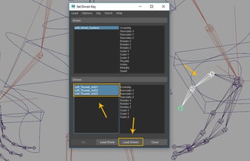
With Left_Wrist_Control selected, click on Load Driver button in the
Set Driven Key window.
Set Driven Key window
Step 3
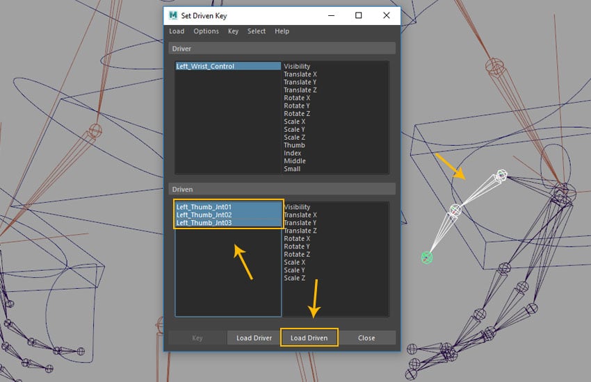
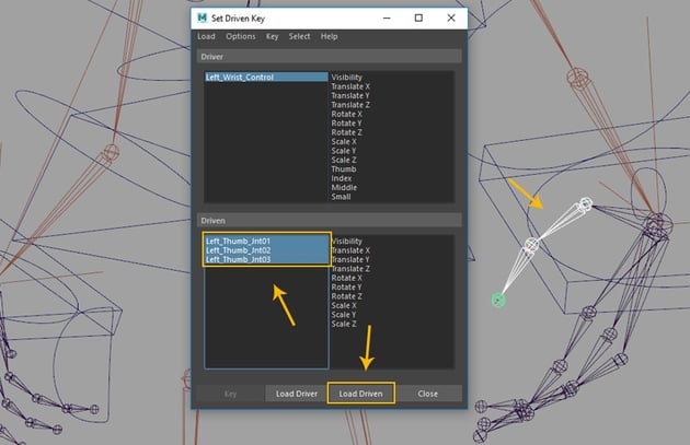
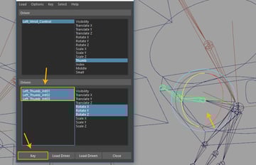
Select Left_Thumb_Jnt01, Left_Thumb_Jnt02 and Left_Thumb_Jnt03 together and then click on Load Driven button as shown in the following image.
Load Driven button
Step 4
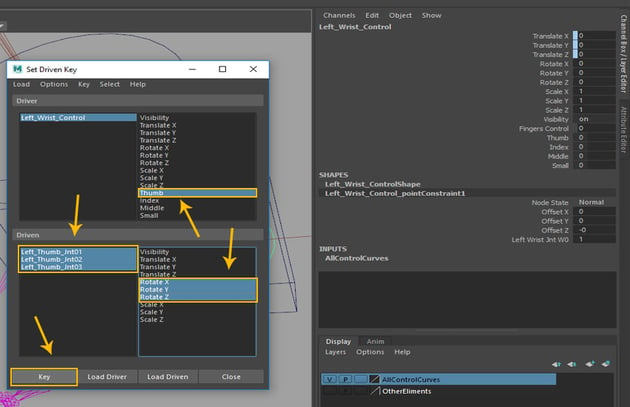
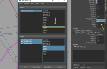
Select Thumb attribute in the Driver group followed by all thumb
joints with their Rotate X,Y and Z properties respectively and then click on Key button to set the initial key.
Driver group
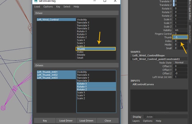
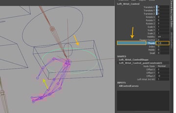
Step 5
With Thumb attribute selected, set its value to -5 in the channel editor as shown in the following image.
Thumb attribute
Step 6
Select all thumb joints followed by Rotate
X, Y and Z attributes and then rotate the joints a little bit outwards. Click on Key button in Set Driven Window as shown in the following image.
Set Driven Window
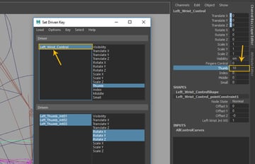
Step 7
With Thumb attribute selected, set its value to 10 in the channel editor.
Thumb attribute
Step 8
Select all thumb joints followed by Rotate X, Y and Z attributes and then rotate the joints a little bit inwards. Click on Key button in Set Driven Window as shown in the following image.
Set Driven Window
Step 9
For checking the thumb attribute after keying, first select the thumb attribute in the channel editor and then drag it in left direction towards the view port with the middle mouse button to slide its value.
Thumb attribute
Step 10
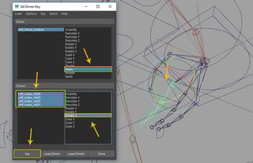
First select Index custom
attribute in Driver group and load it as driver. In the driven group, select all Index joints and then load it
as driven group. Click on Key
button for adding initial key as previously done for thumb.
Driver group
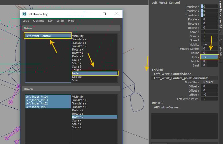
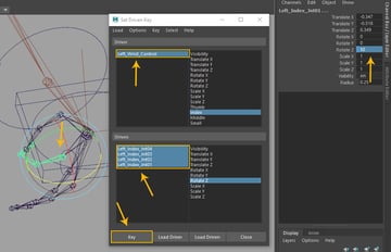
Step 11
With Index attribute selected, change its value to -5 in the channel editor as shown in the following image.
Index attribute
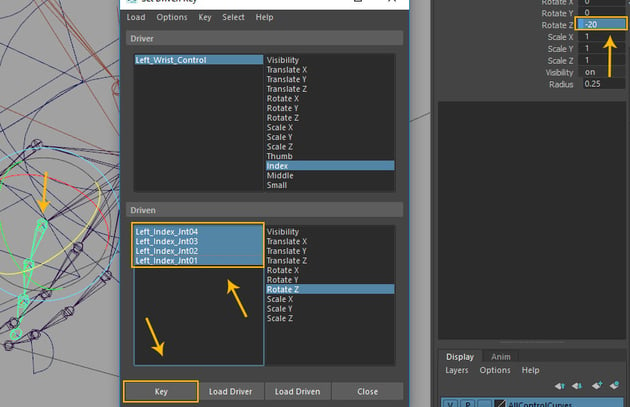
Step 12
With all index finger joints selected, set the value of Rotate
Z axis to -20 to reverse the joints outwards. Click on Key button
to add key.
Click on Key button
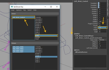
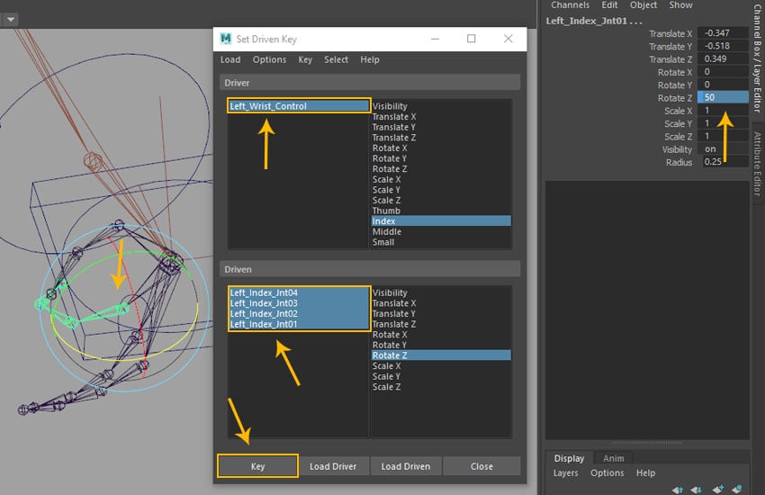
Step 13
With the same Index attribute selected, set the value to 10. With all index
joints selected, set the Rotate Z value to 50 and then click on Key button to add key.
Index attribute
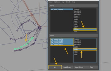
Step 14
First select Middle custom
attribute in Driver group and load it as driver. In the Driven group, select all middle joints and load them as driven group. Click on Key
button to add the initial key as previous done for thumb and Index.
Driven group
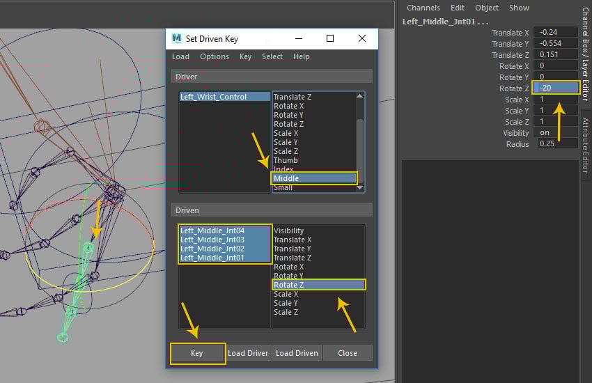
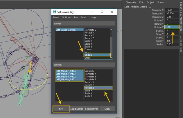
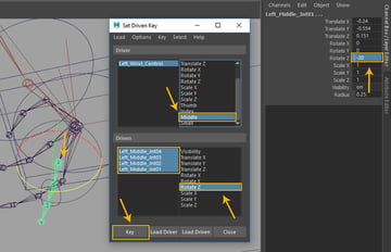
Step 15
Set Middle attribute
value to -5 and then with all middle joints selected, set the RotateZ value to -20. Click on Key
button as shown in the following image.
Middle attribute
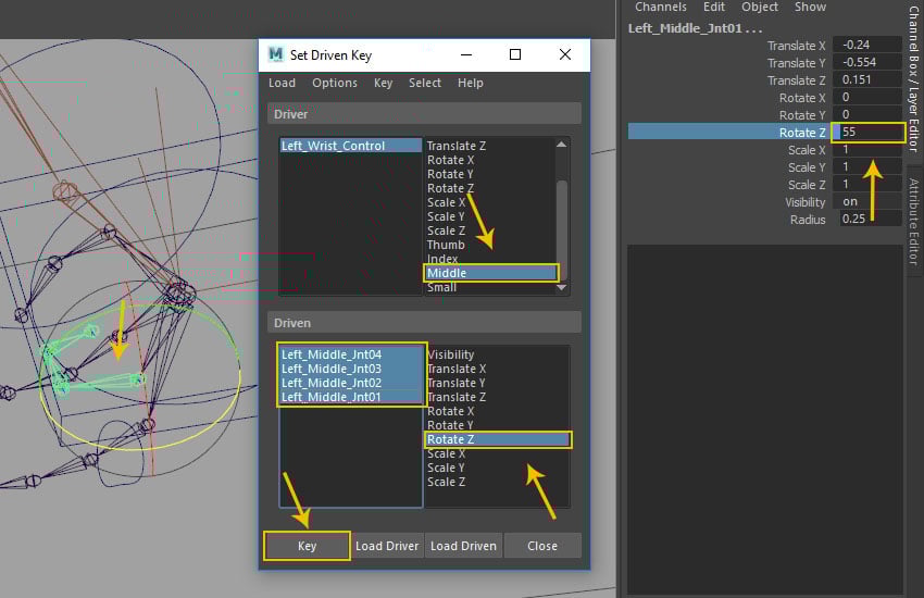
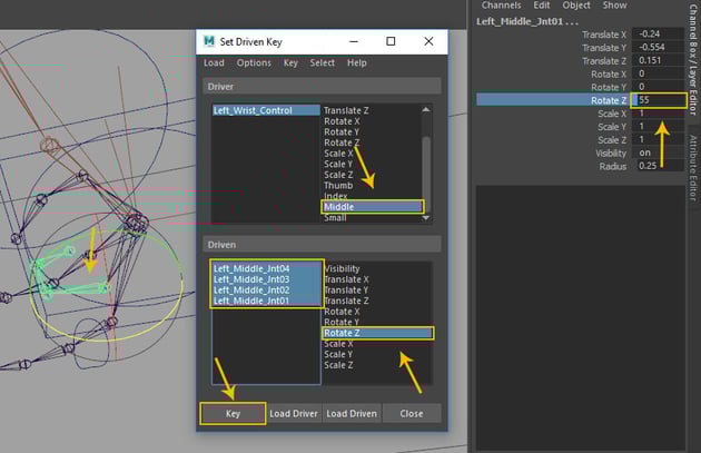
Step 16
Set Middle attribute value to 10 and then with all middle joints selected, set the Rotate Z value to 55.Click on Key button to
add key.
Middle attribute
Step 17
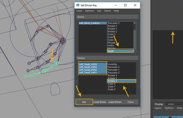
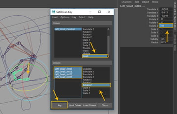
With Small attribute selected in Driver group, select all small
finger joints and Rotate Z
attribute in Driven group and then click on Key
button as shown in the following image.
Small attribute
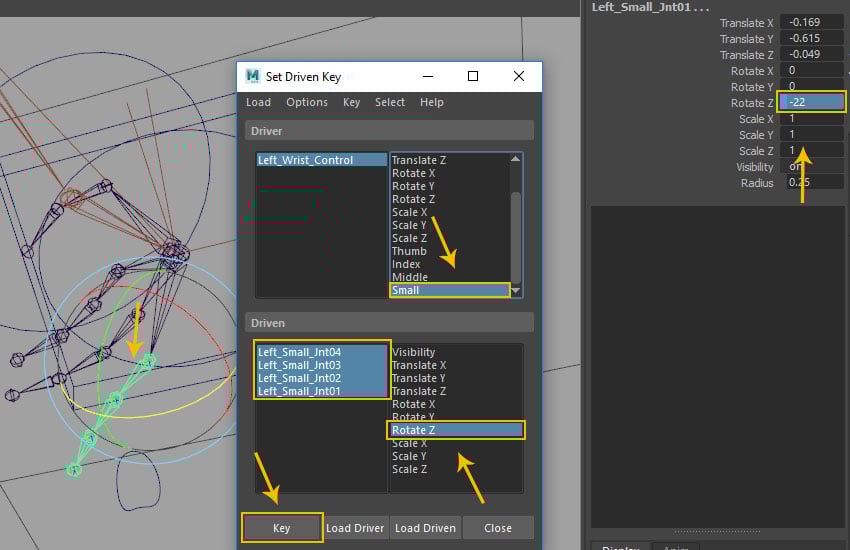
Step 18
With same Small attribute selected, set the value to -5. With allmiddle joints selected, set Rotate Z value to -22 and then click on Key button to
add key.
Small attribute
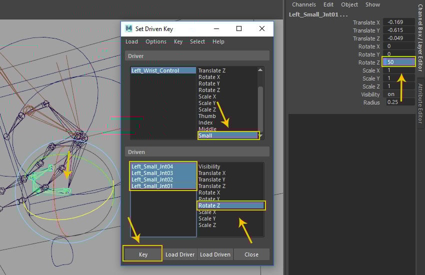
Step 19
With same Small attribute selected, set the value to 10. With allmiddle joints selected, set Rotate Z value to 50 and then click on Key button to add key.
Small attribute
Step 20
Now you have
completed driven keys for fingers and also created variation for all finger attributes. You have got the initial opening and final closing positions for the finger joints.
Opening and closing key
Step 21
In same way
you have completed the right side's hand controls.
Right side's hand controls
Step 22
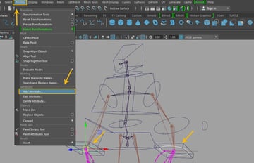
With both wrist control curves selected, go to Modify >Add Attributes option command.
Modify > Add Attributes option
Step 23
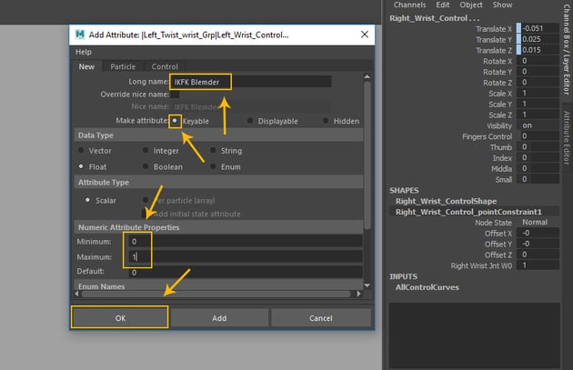
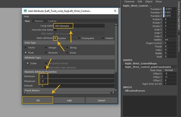
In the
Add Attribute window, write Log name as IKFK Blender and then turn on Keyable radio button. In the Numeric Attribute Properties tab, set Minimum to 0, and Maximum to 1. Click on OK button to create custom attribute.
Add Attribute window
Step 24
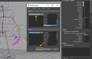
In the Set Driven Key window, load Left_Wrist_Control in Driver group as shown in the following image.
Set Driven Key window
Step 25
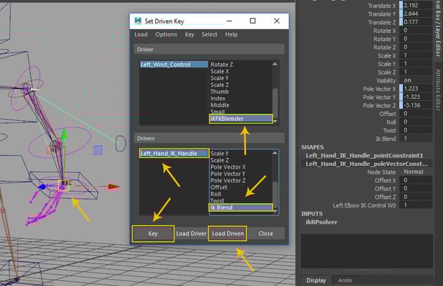
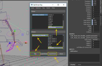
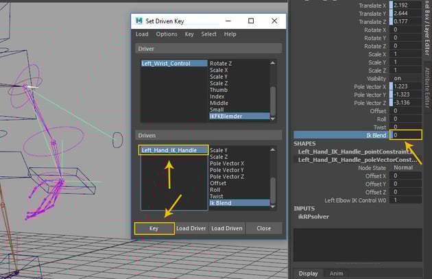
With Left_Hand_IK_Handle selected in the
Driven group, click on Load Driven button. With IK Blend and IKFKBlender attribute selected, click on Key button to add initial key.
Left_Hand_IK_Handle
Step 26
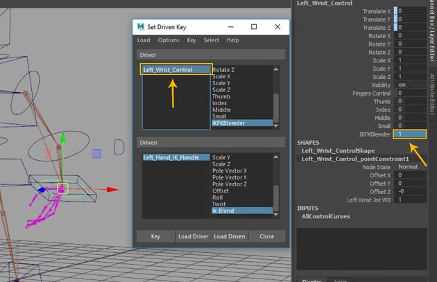
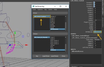
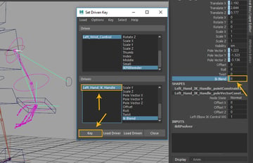
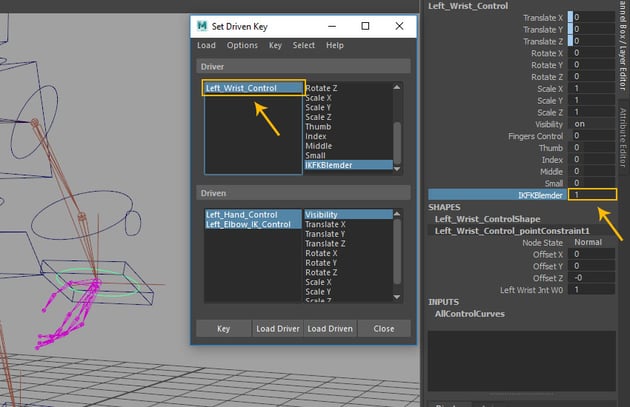
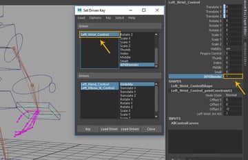
In the
set driven key window, select Left_Wrist_Control and then set the value of IKFKBlender custom attribute to 1.
Left_Wrist_Control
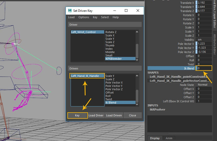
Step 27
With Left_Hand_IK_Handle selected, set the value of IK Blend to 0 and then click on Key button as shown in the following image.
Left_Hand_IK_Handle
Step 28
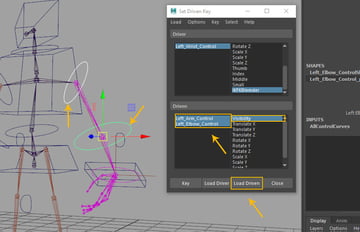
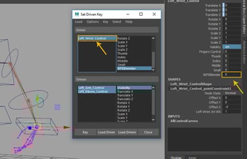
With Left_Arm_Control, Left_Elbow_Control and Visibility attributeselected, click on Load Driven button.
Load Driven button
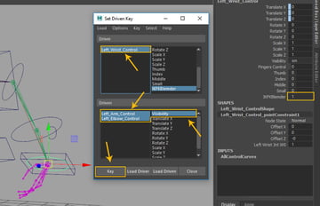
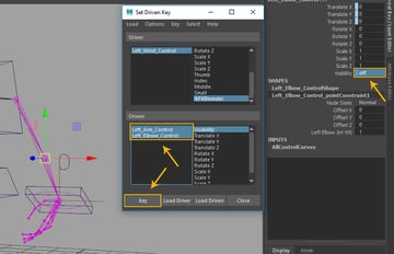
Step 29
With Left_Wrist_Control selected, set the value of IKFKBlender attribute to 1. Select Left_Arm_Control and Left_Elbow_Control followed by Visibility
attribute and then click on Key
button to add key.
Visibility attribute
Step 30
With Left_Wrist_Control selected, set the value of IKFKBlender attribute value to 0.
Left_Wrist_Control
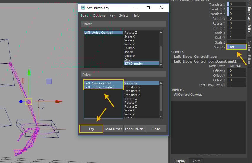
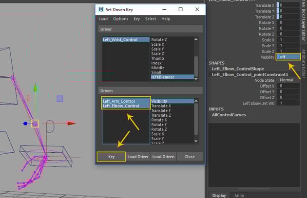
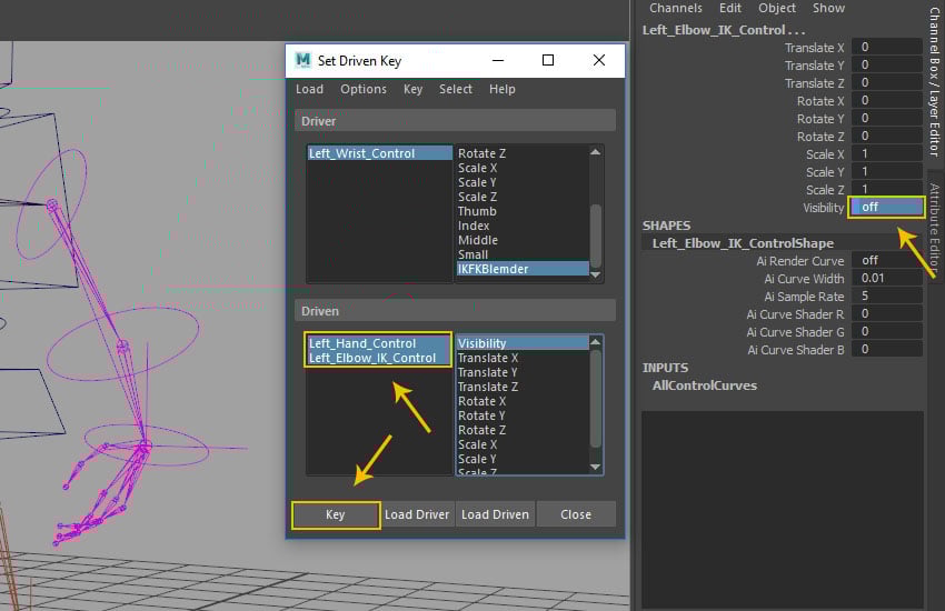
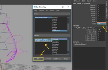
Step 31
With Left_Arm_Control and Left_Elbow_Control selected, set the value of Visibility attribute off and then click on Key button to add key.
Visibility attribute
Step 32
With Left_Wrist_Control selected, set the value of IKFKBlender attribute to 1.
Left_Wrist_Control
Step 33
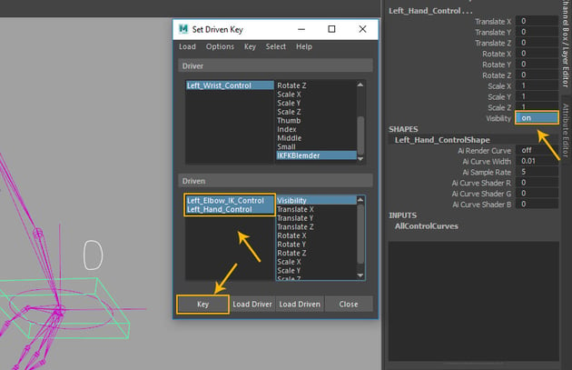
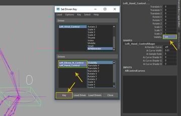
With Left_Hand_Control and Left_Elbow_IK_Control selected, set the value of Visibility attribute off and then click on Key button to add key.
Visibility attribute
Step 34
With Left_Wrist_Control selected, set the value of IKFKBlender attribute to 1. With Left_Hand_Control and Left_Elbow_IK_Control selected, set the value of Visibility attribute on and then click on Key button to add key. In this way, we have completed both side's hand controls.
Visibility attribute
Conclusion
In the next part of the tutorial, I'll show you how to skin the mesh with the joints.


 By
By


