


The following tutorial is based on a real project. This unique tutorial will take users through the real process of creating shaders with bespoke physical properties and applying textures based on real photo references. The subsequent stage will introduce users to the fascinating process of creating and matching the overall lighting closely to the original photo reference supplied by the client while using state-of-the- art techniques to achieve fast and convincing results.
The final step will navigate users through the intricacies of using the best post-production approaches to help enhance and finalize the 3d shot at the highest level.
Most post-production effects implemented in this tutorial are kept in layers with their respective masks to achieve the ultimate control over the final results.
Also available in this series:
- Achieving 3D Realism: Reception Area Render With 3D Studio Max & V-Ray, Part 1
- Achieving 3D Realism: Reception Area Render With 3D Studio Max & V-Ray, Part 2
- Achieving 3D Realism: Reception Area Render With 3D Studio Max & V-Ray, Part 3 Lighting And Rendering
- Achieving 3D Realism: Reception Area Render With 3D Studio Max & V-Ray, Part 4 Lighting And Rendering
- Achieving 3D Realism: Reception Area Render With 3D Studio Max & V-Ray: Post Production
- Achieving 3D Realism: Reception Area Render With 3D Studio Max & V-Ray: Final Post Production
Lighting & Rendering Continued
Create (i.e. copy instance) a few more lights across the scene and test render. When creating the extra lights, ensure to have them next to objects (i.e. walls, etc) so the light web patterns can be visible. See fig.65.0
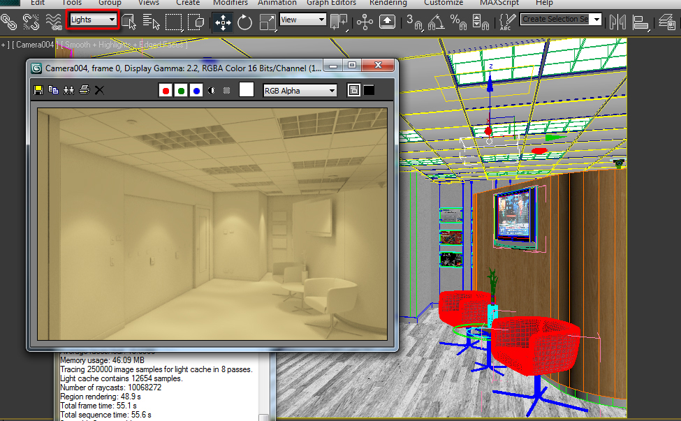
Fig 65.0 - Click To Enlarge
66. To add more contrast to the scene (i.e. depth), decrease the secondary bounces “multiplier” to about 0.8. Test render the results. See fig.66.0

Fig 66.0 - Click To Enlarge
67. The render is looking much better now. Now is the time to see the first test render without the override material.
Disable the “override mtl” and test render. See fig.67.0

Fig 67.0 - Click To Enlarge
68. The full test render is coming out ok and taking slightly longer to render.
Next, we are going to add some tones of blue coming from outside (environment lighting/sky light) to make the render resemble closer to the photo reference.
A- Create a standard “vraylight” object.
B- In “general parameters” change its type to “dome”. This will create a really nice environment light in the scene.
C- Next, rename this new dome light as “VRayLight_Dome”. Also, change its current white colour to a nice tone of blue (R=36; G=98; B=168).
D- Increase its multiplier to about 75.0 to make it cause more impact in the scene.
E- In the “options” group, make the dome light to: cast shadows; invisible; ignore light normal and only affect diffuse. Test render the results. See fig. 68.0, 68.1, 68.2 and 68.3

Fig 68.0 - Click To Enlarge


Fig 68.1


Fig 68.2


Fig 68.3
69. The render is now looking a lot closer to the photo. The next final stage is to increase the render settings and the output image size for final tweaks, using region renders.
A- In “render setup” dialog, open the “v-ray” tab and the “v-ray adaptive DMC image sampler” rollout.
B- So far the renders have been draft; to increase the overall quality, disable the “use dmc sampler thresh” function, and reduce the “clr thresh” value to 0.003. High values yield draft results and lower values yield high/sharp results.
With value of 0.003 the render will take slightly longer to render. See fig. 69.0


Fig 69.0
70. Next, in the “indirect illumination” tab, change the irradiance map “current preset” to “medium”.
Also, in the “v-ray light cache” rollout, increase the “subdivs” value to about 2000. This value should be sufficient to override any light cache artifacts. See fig.70.0 and 70.1


Fig 70.0


Fig 70.1
71. To begin test rendering big region renders, we will do the following:
A- In the “common” tab, under the “area to render” group; change the view to “region” type.
B- A square/rectangle marque should appear in the viewport. Move and adjust it to fit the left most part of the viewport. That area was chosen simply due to the fact that most artifacts are visible in indirectly lit areas of the scene.
C- In the “output size” group, change the “width” and “height” to 2500x1660 and test render. See fig.71.0

Fig 71.0 - Click To Enlarge
72. As anticipated, there are some artifacts (splotches) in the rendered region.
To correct this, simply increase the irradiance map “interp. Samples” to about 85. See fig.72.0


Fig 72.0
73. Also, region render other areas of the scene to check for any possible artifacts and/or to improve the final result.
One of the most common things that reputable companies do at this stage is to:
A- Increase glossy highlights where necessary: glossy highlights are apparent in most real photos, so it’s imperative to try to simulate this effect directly from 3Ds max.
Use some of the techniques covered earlier to increase the glossy highlights of objects such as the curved wooden wall, table legs, etc.
B- Tweak and/or add bump to objects such as the chair, wall, etc.
C- Fine tune reflections as they are imperative in making an image appealing.
D- Etc.
See fig.73.0 and 73.1


Fig 73.0


Fig 73.1
74. Once all the final tweaks are addressed, the final step is to add the render elements, save the irradiance map/light cache and send the final render.
In real projects, while it’s possible to achieve most effects directly from 3Ds Max, most professional companies and individuals choose to save out render elements/passes to help facilitate the post process of editing/enhancing the render at client’s discretion.
This workflow will help the user and the client to tackle specific changes more quickly and efficiently.
A- In the “render setup” dialog, open the “render elements” tab.
Often, companies would add elements such as “zdepth”, “vrayextratex_map” with “vraydirt”, “vraywirecolor”, etc. However, for this exercise we are only exporting the “vraywirecolor” element.
The reason being is that, it only makes sense to save the “zdepth” element when there are objects in the foreground or when rendering close up shots.
Furthermore, the only time professionals use the “vrayextratex_map with “vraydirt” is for interior scenes with too many reflections or/and for exterior scenes. This interior scene has the AO (ambient occlusion) enabled for the entire scene already; therefore adding an extra AO element on top will make the image look too “artistic” and “game like”.
B- To add the “vraywirecolor” element, click on the “add” toggle to bring up its dialog.
C- Scroll down the dialog and choose the “vraywirecolor” element from the list. This render element renders the physical wire colours of the objects in scene (i.e. similar to material and object ID colours).
For this reason, it’s essential to ensure that every object in the scene with a different material has a different wire colour object applied to. See fig.74.0 and 74.1

Fig 74.0 - Click To Enlarge

Fig 74.1 - Click To Enlarge
75. To save the irradiance map and the light cache for “network rendering” or consistent renders, one should do the following:
A- In the “v-ray” tab, scroll down to the “v-ray global switches” rollout.
B- In the “indirect illumination” group, turn on the “don’t render final image” option. This function will ensure that the pre-render process will stop once the calculations are saved.
C- Open the “indirect illumination” tab and scroll down to the “v-ray irradiance map” rollout.
D- In “on render end” group enable the “auto save” function and click on the “browse” toggle.
E- Name your Irradiance map file and save it to close the “save irradiance map” dialog.
F- Also, enable the “switch to saved map “option. Once the pre-calculation process is completed/saved, this function will automatically locate and ask the user to load the saved irradiance map. Repeat the all the previous actions for the light cache parameters. See fig. 75.0, 75.1 and 75.2


Fig 75.0

Fig 75.1 - Click To Enlarge


Fig 75.2
76. Once the pre-calculation process is finished, the “load irradiance map” dialog should be prompted to open the pre-saved irradiance map.
Select and open the relevant file to close the dialog. The irradiance and light cache map should automatically change to “from file” mode.
Also, go back to the “v-ray global switches” and turn off the “don’t render final image” function. See fig.76.0, 76.1, 76.2 and 76.3

Fig 76.0 - Click To Enlarge


Fig 76.1


Fig 76.2


Fig 76.3
77. Before sending the final render, change the “area to render” to “view” type.
Also, enable and name the “render output”.
Finally, set the save as type to TGA (targa 32 bits-per pixel; compress; pre-multiplied alpha).
While some users prefer to save their renders as an EXR file type, I personally have fewer problems editing TGA files in post than EXRs. However, feel free to use whatever file format you’re most comfortable with.
It is worth noting that at times the “vraywirecolor” element may render with small dots (artifacts) in the 3Ds Max frame buffer. However, when the same file is opened in Photoshop, it should appear without such artifacts. See fig. 77.0 and 77.1

Fig 77.0 - Click To Enlarge
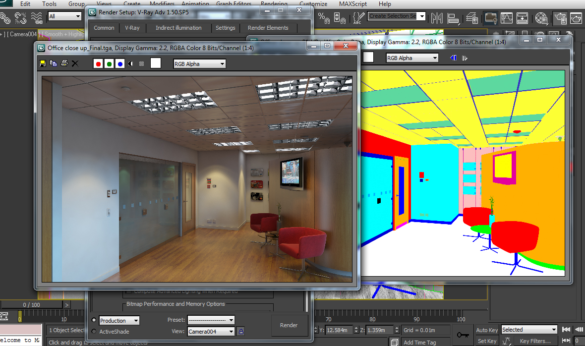
Fig 77.1 - Click To Enlarge
Conclusion: this penultimate chapter focused on the process of creating ies lights and editing its numeric ies web values. Furthermore, users were also introduced to the unique workflow of quickly and efficiently lighting an interior scene while creating a nice and balanced render with key GI parameters (i.e. Depth). Additional adjustments were also made to rectify artifacts and to enhance key parameters for optimal results.
Stay tuned for part 5!
 By
By


