


The following tutorial is based on a real project. This unique tutorial will take users through the real process of creating shaders with bespoke physical properties and applying textures based on real photo references. The subsequent stage will introduce users to the fascinating process of creating and matching the overall lighting closely to the original photo reference supplied by the client while using state-of-the- art techniques to achieve fast and convincing results.
The final step will navigate users through the intricacies of using the best post-production approaches to help enhance and finalize the 3d shot at the highest level.
Most post-production effects implemented in this tutorial are kept in layers with their respective masks to achieve the ultimate control over the final results.
Also available in this series:
- Achieving 3D Realism: Reception Area Render With 3D Studio Max & V-Ray, Part 1
- Achieving 3D Realism: Reception Area Render With 3D Studio Max & V-Ray, Part 2
- Achieving 3D Realism: Reception Area Render With 3D Studio Max & V-Ray, Part 3 Lighting And Rendering
- Achieving 3D Realism: Reception Area Render With 3D Studio Max & V-Ray, Part 4 Lighting And Rendering
- Achieving 3D Realism: Reception Area Render With 3D Studio Max & V-Ray: Post Production
- Achieving 3D Realism: Reception Area Render With 3D Studio Max & V-Ray: Final Post Production
Lighting & Rendering
Lighting plays a unique and important role in bringing the scene to life. As such, it is vital to take the necessary steps to plan and create the type of lighting that will be appealing and complementary to the scene.
Colors emitted by the lights are also crucial in setting up the mood of the scene. For instance professional artists tend to use blue and yellow color pallets as they frequently work well together.
For this scene, a cold blue color coming from windows can be generated by the ambient light of the skylight object; and a warm yellow color can be generated by the ceiling lights to create a nice and balanced render.
52. Without further a do we are going to start by applying a simple override material to the entire scene, for quick rendering turnarounds.
Next, we will create the lights and enable the GI. Once satisfied with the overall results, the override material will be disabled in order to address the final tweaks and send the final render:
A - Create a new v-ray material slot in the material editor and name it “override material”.
B - Open the “render setup” dialog (f10).
C - In the “v-ray” tab, open the “v-ray global switches” rollout.
D - In the “materials” group enable the “override mtl” function.
E -Back in the material editor dialog, drag the new material override and drop it onto the “override mtl” toggle. Accept the “instance” copy method. See fig.52.0
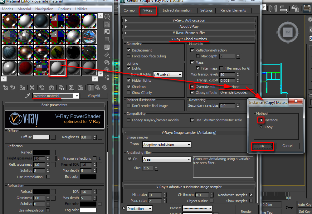
Fig 52.0 - Click To Enlarge
53. In the “V-Ray image sampler (anti-aliasing)” rollout, change it to “adaptive subdivision” type. This anti-aliasing is simple and yet very effective to achieve superior results.
Its default settings are set to draft.
Scroll further down to the “v-ray color mapping” rollout. Change the current “color mapping” to “exponential” type, and set it to “affect background” only. This will prevent the bright spots from becoming overexposed. See fig. 53.0; 53.1 and 53.2


Fig 53.0


Fig 53.1


Fig 53.2
54. Test render to see the initial results.
The scene rendered very quickly. However, it still looks very flat. The next step is to enable the global illumination (GI), change some of its default high settings for fast GI results, and improve the overall render.
A - In “indirect illumination” tab, enable the GI.
B - Also, turn on the “ambient occlusion” function. Change the distance to about 0.7 and the “radius” to about 0.3m.
These values always worked wonderfully with real scale models. However, you may try different values, if desired.
C - Next, change the secondary bounces to “light cache”. While default “brute force” gi engine is simple and accurate, it is very time consuming to render.
D - In “v-ray irradiance map” rollout, change the “current preset” to “very low”. At this preliminary stage of creating and tweaking lights, it would be counterproductive to work with “high” pre-sets. Also, in the “options” group, enable the “show calc. phase” and “show direct light” functions. These two functions will enable the user to see in the frame buffer those two options being computed during the pre-calculation time. See fig.54.0


Fig 54.0
55. Next, we are going to change the “light cache” parameters to draft.
A - Scroll further down to the “v-ray light cache” parameters rollout. Change its “subdivis” value to 500. This lower value will speed up the light cache calculation time.
B - Enable the “store direct light”, “show cal.phase” and the “pre-filter” functions. See fig 55.0


Fig 55.0
56. Test render the results.
With the GI enabled, the render looks completely dark now. The next step is to begin creating lights.
A - In the “command panel”, select the “lights” set, followed by choosing “vray” from the dropdown list type.
B - I the v-ray “object type” rollout, select the “Vray ies” type.
C - Click and drag it in the “front” viewport to create it.
D - Once created; disable the “targeted” function, for more flexibility to move the light around the scene.
E - Move the light close to the far left ceiling light model in the camera view(x=42.092m; y=13.219m; z=2.527m). Test render to see the results. See fig.56.0; 56.1; 56.2 and 56.3.


Fig 56.0


Fig 56.2 - Click To Enlarge

Fig 56.3 - Click To Enlarge
57. The scene is slightly brighter now.
The next task is to apply an ies web file with patterns to make the scene more appealing.
While in reality the lights cast by the current light model would simply wash down the walls, the client had decided to use a really nice web file to make the image more appealing.
In order to preview and choose the correct light web file, we are going to create a standard photometric light and turn off all its parameters. This light will be used only to preview the light web file.
A - Create a standard photometric light.
B - Open the “modify” command panel and turn it off to prevent it from having any effect in the scene.
C - In the “light distribution (type)”, choose the “photometric web” type and click on its toggle to preview the web file pattern to choose from.
Pick the web file under the name of “10.ies”. See fig.57.0 and 57.1.

Fig 57.0 - Click To Enlarge
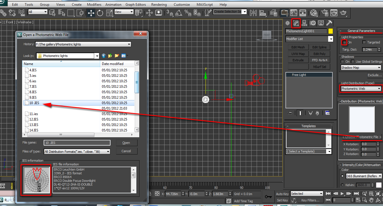
Fig 57.1 - Click To Enlarge
58. Select the v-ray ies light and pick the same light web file (i.e. 10.ies).
Also, reduce the “shadow bias” value to 0.0m. This will ensure that even tiny objects cast shows. Test render the results. See fig.58.0

Fig 58.0 - Click To Enlarge
59. Copy “instance” another light to the far right side of the camera viewport (x=42.088m; y=15.181m; z=2.527m). Test render again. See fig.59.0 and 59.1


Fig 59.0
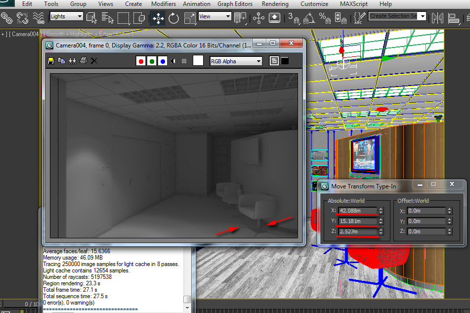
Fig 59.1 - Click To Enlarge
60. The scene is looking much better now. However, the shadows are slightly sharp.
Soft shadows are usually more appealing in most visuals. The next step is to soften the shadows by editing its numeric values.
A - Open the notepad dialog by clicking on windows “start” button and typing in “notepad”. Open the “notepad” dialog.
B - Locate the relevant ies web file in the respective folder.
C - While the “notepad” dialog is still open; drag the “10.ies” web file from the folder into the notepad dialog. Its numeric values should appear.
To soften the shadows there are only three values to change. These values are often the three zeros that appear after the numbers 1, 1 and 2. See fig.60.0 and 60.1


Fig 60.0
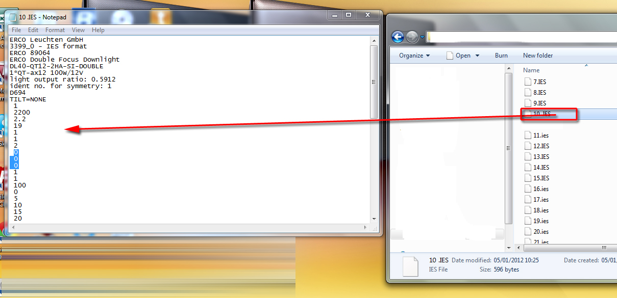
Fig 60.1 - Click To Enlarge
61. Change those three zeros to 0.5; 0.5 and 0.5. These values worked well for the level of softness intended. However, you may enter different values if desired. See fig. 61.0


Fig 61.0
62. The next phase is to save this edited file under a different name.
A - Click on the “file save as” option.
B - Change the “save as type” to “all files”.
C -In the dialog, select the “10.ies” web file from its location.
D - Rename its file name as “10._1.ies” and “save” it. See fig. 62.0 and 62.1


Fig 62.0
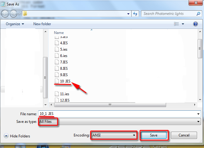
Fig 62.1- Click To Enlarge
63. Back in the 3Ds Max file, replace the current web file to newly created one (i.e. 10_1.ies). See fig. 63.0

Fig 63.0 - Click To Enlarge
At times, one may be required to replace the new ies web file twice in order for the changes to occur. Test render the results.
64. The shadows are much softer now. The next step is to increase the “power” of the light and change its colour to match closer photo reference.
A - In the light’s “color” swatch, change it to a yellow tone(R=243; G=178; B=65).
B - Also, increase its “power” to 4200.0. Test render the changes. See fig. 64.0
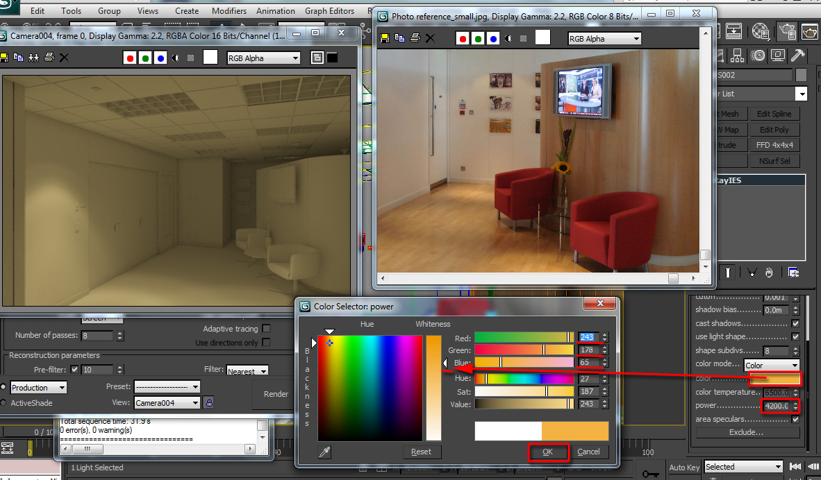
Fig 64.0 - Click To Enlarge
65. The scene is looking more appealing now. Change the selection filter type to “lights”. This will ensure that only lights are selected in the scene.
Finally, test render each and every light created prior to creating the next one.
This is to ensure that lights are NOT too close from one other; and that there is a clear definition/contrast between dark and bright areas in the scene (i.e. Depth).
This technique will also prevent the scene from suddenly becoming “bleached out”.
Stay tuned for part 4!
 By
By


